DLPU066A March 2018 – April 2022 DLP3030-Q1
1.1 Calibration Purpose
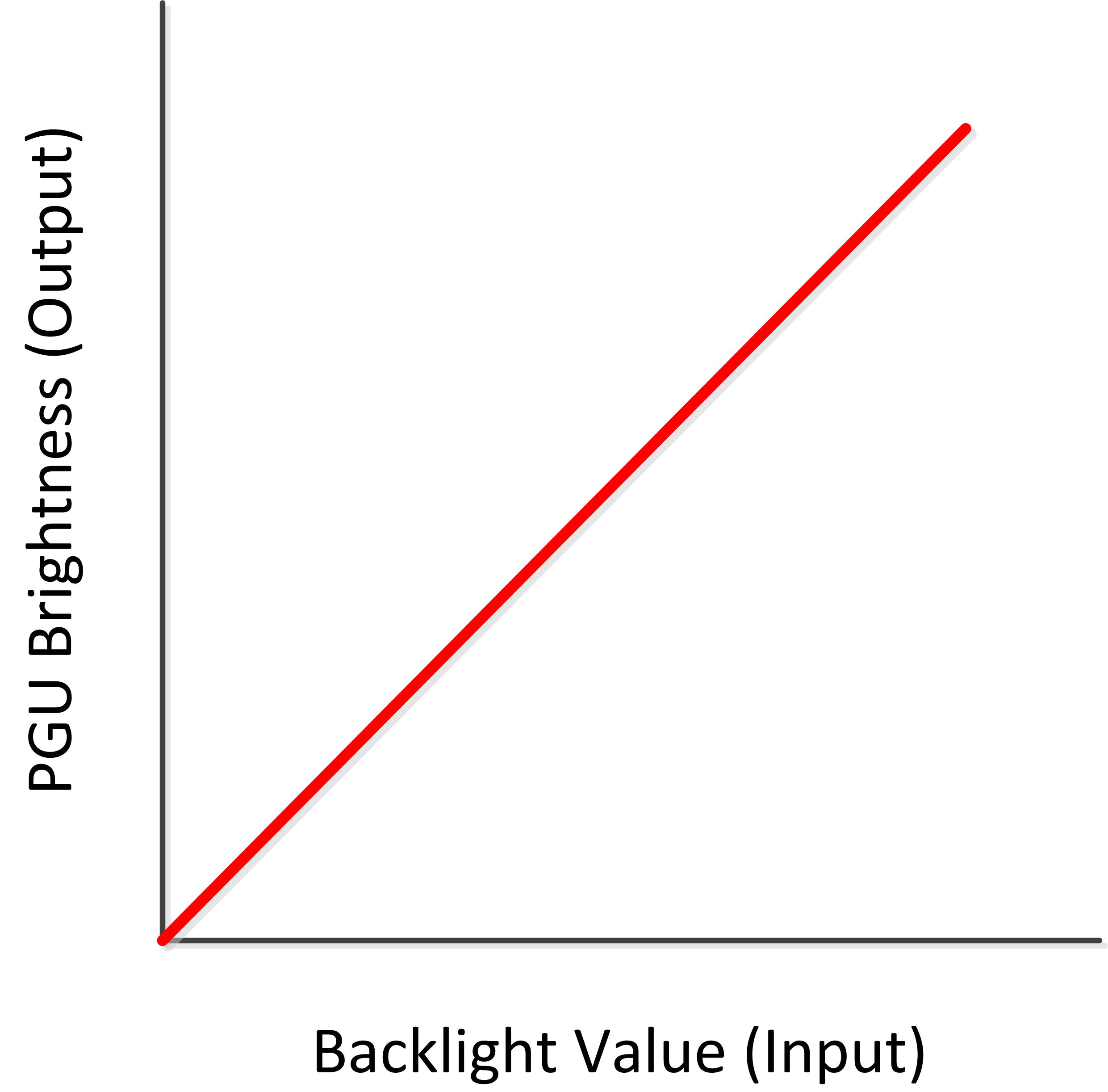
DLP3030-Q1 based PGUs must be calibrated in order to ensure that the color point of the HUD is maintained across its operating conditions, which include a 5000:1 dimming ratio and –40°C to 105°C operating temperature. Additionally, the HUD must be calibrated to achieve smooth dimming, meaning the output brightness of the system should change linearly with the input brightness as in Figure 1-1.
 Figure 1-1 Backlight Value vs PGU Brightness
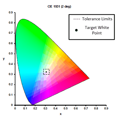
White point of a PGU determines the ratio of red, green, and blue for a desired output. The target white point is specified as an x,y coordinate pair in the CIE 1931 color space chromaticity diagram shown in Figure 1-2. The wavelength of light output from the LEDs changes as the junction temperature changes, so calibration is required to compensate for these shifts. Additionally, a tolerance is limit is provided on the x and y coordinates. The calibration procedure makes sure that the white point of the DLP HUD EVM stays within the tolerance as the input brightness level, referred to as backlight value, is adjusted.
 Figure 1-2 CIE 1931 Color Space Chromaticity Diagram