DLPU105 March 2021 DLP471TP , DLPC6540
PRODUCTION DATA
7 EVM Setup
The DLP LightCrafter Display 471TP EVM is composed of three parts:
- Front-End board
- Formatter Board
- Optical Engine with LED connections and Flex cables
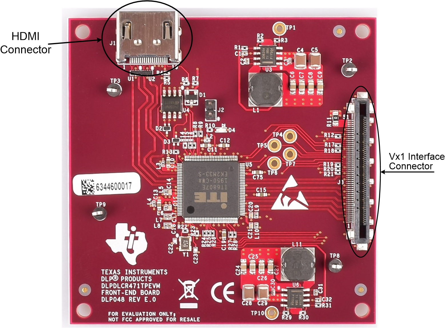
The Front-End board contains the connector for the HDMI input and a flex cable connector for interfacing to Formatter board. Figure 7-1 shows the main connectors on the Front-End board.
 Figure 7-1 DLP LightCrafter Display Front-End Board
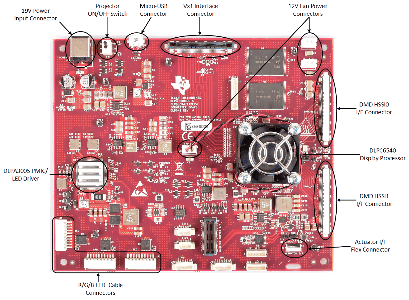
The Formatter board contains connector for the external power supply, a USB connector to communicate to the DLP LightCrafter Display software, the RGB LED connectors, the DMD flex cable connectors, the Front-End Board interface flex connector, and 12 V fan power connectors. The Formatter board also contains a switch to turn on the projector after external power is supplied. The connectors for each LED are labeled on the board as well as on the light engine.
Always ensure a good connection of the flex cables, power cables and LED cables to the Formatter Board before turning the EVM on.
 Figure 7-2 DLP LightCrafter Display Formatter Board