SBAA483 February 2021 ADS1120 , ADS112C04 , ADS112U04 , ADS114S06 , ADS114S06B , ADS114S08 , ADS114S08B , ADS1220 , ADS122C04 , ADS122U04 , ADS124S06 , ADS124S08 , ADS125H02 , ADS1260 , ADS1261 , ADS1262 , ADS1263
- Abstract
- Trademarks
- 1Introduction
- 2Features Used to Detect Wire Breaks in RTD Systems
- 3Wire-Break Detection Methods for Different RTD Configurations
- 4Settling Time Considerations for RTD Wire-Break Detection
- 5Summary
- A How Integrated PGA Rail Detection Helps Identify Wire Breaks
- B Pseudo-Code for RTD Wire-Break Detection
3.2.1.1.1 Detecting a Break in Lead 2 in a One-IDAC, 3-Wire RTD System Using a High-Side RREF
The high-side RREF case requires a diagnostic measurement with several configuration changes:
- Switch IDAC1 to output on lead 2 (AINN)
- Enable IDAC2 to output on lead 3 (AINCOM)
- Select the ADC internal VREF as the reference voltage source
- Select AINN and AINCOM as the measurement inputs (if necessary)
- Reduce the PGA gain (if necessary)
- Reduce the IDAC current magnitude (if necessary)
A different voltage reference source is required in order to check the measurement result for a fault because current cannot be forced through RREF in this case. This action is dissimilar from all other diagnostic measurement routines, and care must be taken to ensure that the external VREF inputs are reselected when the diagnostic cycle completes.
Also, the last three steps are considered if necessary because the system may already be configured as such before the diagnostic measurement begins. For example, a one-IDAC, 3-wire RTD system always requires two measurements for lead resistance cancellation: first, between AINP and AINN and second, between AINN and AINCOM. Therefore, this diagnostic routine can be implemented after the second measurement when AINN and AINCOM are already selected, eliminating some communication and switching time. Moreover, the system may be measuring a large RTD (for example, a Pt1000), where the PGA gain is already set to 1 V/V and the IDAC current magnitude is small. These latter two steps are important for fault detection and are described in more detail later in this section.
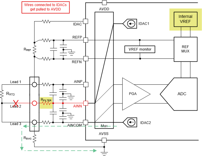
Figure 3-5 shows how to implement the diagnostic measurement for a one-IDAC, 3-wire RTD system using a high-side RREF.
 Figure 3-5 Diagnostic Measurement Checks if Lead 2 is
Broken Using a High-Side RREF
Figure 3-5 Diagnostic Measurement Checks if Lead 2 is
Broken Using a High-Side RREFIf lead 2 is not broken during this diagnostic measurement, expect the following voltages (given by Equation 1 and Equation 2) at the AINx pins:
The resulting differential voltage, VIN (no wire break), between AINN and AINCOM is given by Equation 3, assuming RLEAD2 = RLEAD3, IDAC1 = IDAC2, and the RFILTER resistors are well-matched:
If there is no fault to alter the circuit operation, VIN (no wire break) is a very small voltage because RLEADx is typically less than 10 Ω in most cases.
Comparatively, a break in lead 2 eliminates the IDAC1 path to ground, causing IDAC1 to try to force current into the high-impedance analog input, AINN. The high impedance acts as an open circuit, raising the voltage level on AINN as the IDAC circuitry tries to maintain constant current. Eventually, this voltage is driven to the positive supply (AVDD) such that AINN is now approximately at AVDD as well.
Moreover, the voltage at AINCOM has actually reduced, because IDAC1 is no longer able to flow through RLEAD3 and RBIAS, resulting in an absolute voltage at AINCOM as given by Equation 4:
The resulting differential voltage, VIN (wire break), between AINN and AINCOM is given by Equation 5:
Assuming that a small IDAC2 magnitude is chosen as per the configuration changes discussed at the beginning of this section, VIN(wire break) is significantly larger than VIN(no wire break) and therefore easy to detect. In order to quantify what is meant by a small IDAC2 magnitude, consider the AVDD voltage as well as the size of RFILTER and RBIAS in the system, which are typically on the order of 1 kΩ to 5 kΩ each. For example, if AVDD = 5 V, RFILTER = 5 kΩ, and RBIAS = 2 kΩ, selecting an IDAC magnitude of 100 µA is a good starting point. Assuming that RLEADx = 10 Ω, these values can be entered into Equation 6 and Equation 7 to determine if the results clearly indicate when a fault has occurred:
For this example, set the PGA gain to 1 V/V in order to measure VIN (wire break) without saturating the amplifier. The specific gain required for the system ultimately depends on the different resistance values, AVDD, and the IDAC current magnitude chosen, so take care to select these values appropriately.