SBAU416B November   2022  – January 2024 ADS9813


  1.   1
  2.   Abstract
  3.   Trademarks
  4. 1Overview
    1. 1.1 ADS9813EVM and ADS9817EVM Features
  5. 2ADS9813EVM and ADS9817EVM Quick Start Guide
  6. 3Analog Interface
    1. 3.1 ADC Input SMA Connections
    2. 3.2 Voltage Reference
  7. 4Digital Interface and Clock Inputs
    1. 4.1 Digital Interface Connections
    2. 4.2 Clock Select
  8. 5Power Supplies
    1. 5.1 USB Power and When to Power the Board Externally
  9. 6ADS9813EVM and ADS9817EVM Software Reference
    1. 6.1 ADS9813EVM-GUI and ADS9817EVM-GUI Software Installation
    2. 6.2 USB Driver Installation
    3. 6.3 Using the CONFIG Tab
    4. 6.4 Using the Capture Tab
    5. 6.5 Using the INL/DNL Tool
    6. 6.6 Using the Histogram Tab
  10. 7Schematics, Layouts, and Bill of Materials
    1. 7.1 Schematics
      1. 7.1.1 ADS9813EVM Schematics
      2. 7.1.2 ADS9817EVM Schematics
    2. 7.2 Layout
    3. 7.3 Bill of Materials (BOM)
      1. 7.3.1 ADS9813EVM Bill of Materials (BOM)
      2. 7.3.2 ADS9817EVM Bill of Materials (BOM)
  11. 8Revision History

Using the INL/DNL Tool

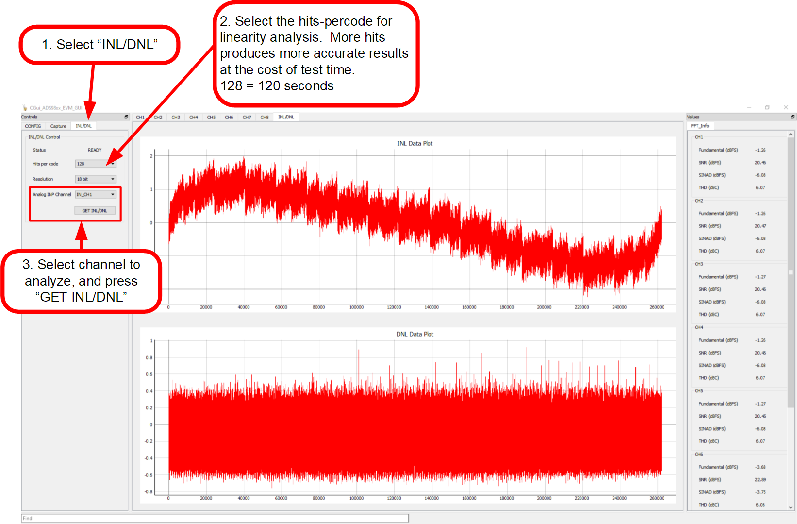
The INL/DNL tool measures the linearity of the of the ADS9813EVM or ADS9817EVM by applying a full-scale, low-distortion sinusoidal input signal. The accuracy improves if the number of hits per code is increased at the cost of extra test time. Select the channel to measure and the hits per code. An input signal greater than full-scale is required to verify that all ADC codes are tested. An input signal of +0.1 dBFS is sufficient. Then press the GET INL/DNL button to run this tool as shown in Figure 6-7.
GUID-20221025-SS0I-VGKJ-1PQS-S9LWVKWLCSQQ-low.pngFigure 6-7 Using the INL/DNL Tool