SBOU246 January 2022 TMP61 , TMP61-Q1 , TMP63 , TMP63-Q1 , TMP64 , TMP64-Q1
3.4 Calibration
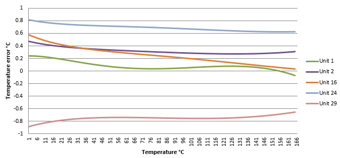
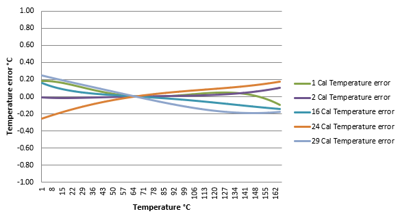
Figure 3-13 shows the accuracy across the temperature range of multiple TMP6 thermistor units. As can be seen in the figure, each units accuracy varies, but shows linearity. Thanks to the high linearity of the TMP6x thermistors and their similarity across units, we can remove the tolerance errors from the thermistor, VCC, VREF, ADC LSB and bias resistor and get a very consistent accuracy across the whole temperature range without additional costs. You will need a high accuracy temperature reference. The TMP117 is a high-accuracy, low-power, digital temperature sensor with a NIST traceable accuracy of ±0.3°C (maximum) from –55°C to +150°C. You will need to add some amount of automation to the process after the firmware has been programmed into the UUT (Unit Under Test). After adding in the calibration, the units are now lined up within ±0.3°C across the temperature range (see Figure 3-14).
 Figure 3-13 TMP6 Thermistor Potential Temperature Error.
  Figure 3-14 TMP6 Thermistor Potential Temperature Error With Correction.
 Process: The production programming device will program the firmware into the UUT. Once the UUT powers up for the first time, the UUT will use its ADC to measure the VSensevoltage from the TMP6x thermistor on the PCB, calculate the temperature, and write the temperature into the temperature register. At this point either the production programming device or the UUT will read the temperature register in the UUT and read the external temperature reference, subtract the measured temperature from the external temperature reference, and write this value into the offset register. For all future temperature measurements the UUT will add the measured TMP6 thermistor temperature value to the offset register value for the final corrected temperature.
Assumptions: The UUT and temperature reference is at ambient temperature. The UUT will be operating at low power during firmware programming. The TMP6x thermistor's temperature will be measured immediately upon power up. The offset will be calculated based on the first temperature measured upon power up and the temperature reference.
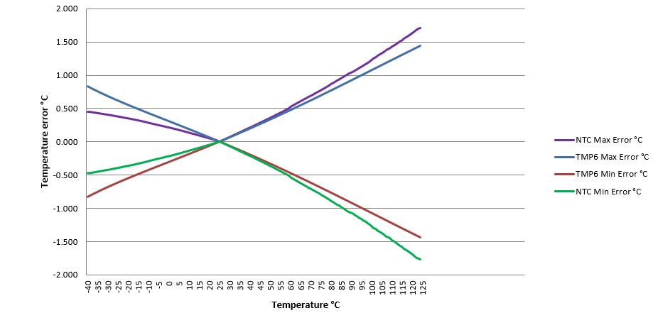
After implementing a single point calibration, a comparison between the accuracy of an NTC thermistor and the TMP61 Linear Thermistor is shown in Figure 3-15.
 Figure 3-15 Offset Corrected Total Thermistor Temperature Error Compared.