SBOU302A June 2023 – December 2023 INA740B , INA745A , INA745B , INA780B
3.1.3.2 GUI to EVM Connection
To connect the GUI to the EVM, follow these steps:
- Setup and launch the GUI as described in Initial Setup.
- Check to make sure that the EVM connected to the GUI.
- Close the README.md file page to initiate the connection. If successful, then the text Hardware Connected is visible near the bottom left corner of the GUI.
 Figure 3-4 Hardware Connected
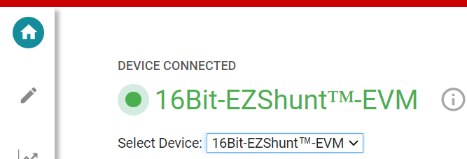
- A green indicator with the device bit type (either
16 bit or 20 bit) appears and the text DEVICE CONNECTED is visible near
the top left of the GUI.
 Figure 3-5 Device Type
Connected
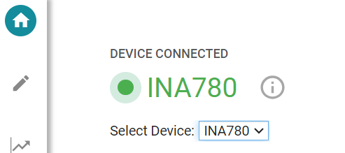
 - From the Select Device drop-down menu, select the specific EVM to be used.
- A green indicator with the device type and the text
DEVICE CONNECTEDis also be visible near the top left of the GUI.
 Figure 3-6 Device
Connected
 - The user needs to update the SW0 (pin A0) and SW1 (pin A1) field values to the values selected on the EVMs SW0 and SW1 address select switches.
- If the text Hardware Connected and
DEVICE CONNECTED does not show in the GUI, then long-press the
RESET button on the EVM to try again.
- If that option does not
work, then check different hardware COM ports under Options >
Serial Port.
Figure 3-7 Change Serial Port
- If that option does not
work, then check different hardware COM ports under Options >
Serial Port.
- If the hardware still does not connect, then make
sure the correct GUI/EVM combination is being used.
- If the user is using the correct GUI/EVM combination, then reprogram the firmware of the SCB as described in Firmware Debug.
- Many connectivity issues
can be addressed by doing one of the following:
- Long-press the
RESET button on the EVM with the EVM and SCB
connected to each other.
- Refreshing the GUI can also sometimes help.
- Connect the EVM
to a different USB port.
- Avoid using long cables and USB hubs.
- If using a desktop PC, then try a USB port on the back.
- Long-press the
RESET button on the EVM with the EVM and SCB
connected to each other.