SLAA913A January 2020 – June 2021
3.2 I2C Protocol and Data Buffering for Low Power
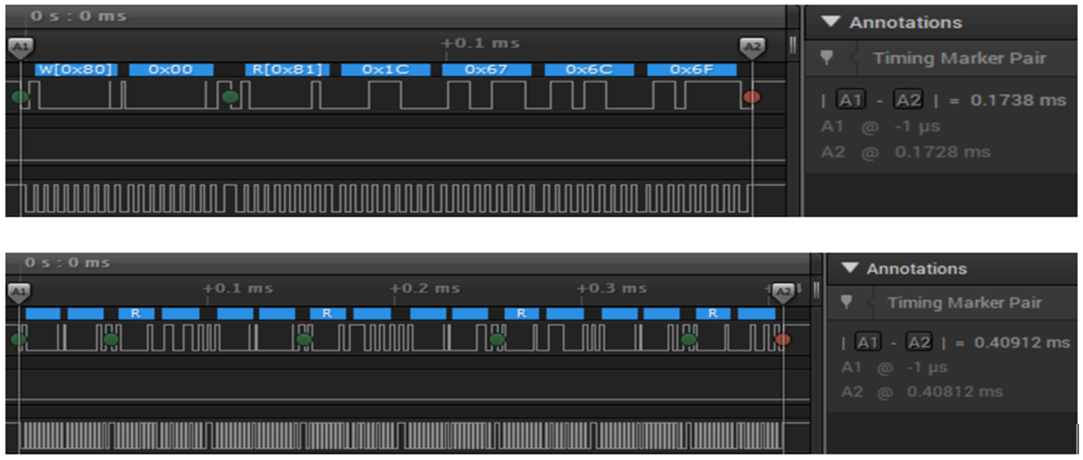
In this design the multibyte read functionality of the HDC2010 sensor is used to reduce the I2C communication time; the difference between single-byte mode and multibyte mode is described in Table 3-2. The multibyte mode requires only one read command with continuous ACK request to read out 4 bytes, which are starting at address 0x00. This helps reduce the code size as well as the I2C communication activity time and the overall system power consumption.
| Master | START | Slave address(W) | Address | Start | Slave address (R) | NACK | STOP | ||||
| Slave | ACK | ACK | ACK | DATA |
| Master | START | Slave address (W) | Address | Start | Slave address (R) | ACK | ACK | NACK | STOP | ||||||
| Slave | ACK | ACK | ACK | DATA | DATA |
In Figure 3-3, the upper image of a Saleae LogicPro16 analyzer displays the multibyte read, with only one write register address command and 4 bytes (Humidity and Temperature values) read out with a total duration of 0.1738 ms. The lower image utilizes a separate write register address command for each byte value to be read out, which lasts for 0.409 ms in total.
 Figure 3-3 Comparison of Four Byte Read Modes (Multibyte Read on Top)
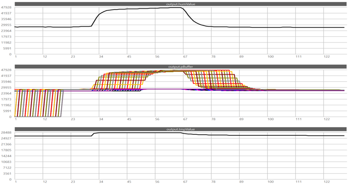
The collected sensor data is written to an user-configurable data buffer area, with the 2 bytes temperature and 2 bytes humidity values stored one after the other. When the desired buffer length is filled up with data, for example, 80 bytes after 20 minutes with 1 readout every minute, the Arm Cortex-M4F MCU is notified to get the data buffer and transmit it. This significantly reduces the protocol overhead, with only the same 8 bytes for preamble and SYNC but now with 80 bytes payload at once.
 Figure 3-4 Temperature and Humidity Data Buffer in Sensor Controller Studio
The data buffer size with 80 bytes is arbitrary and was selected to have a reasonable size for testing purposes. The system designer may increase the buffer size to utilize the maximum available ULL SRAM inside the SCE, which amount to almost 3K bytes, see the resource allocation for the provided CC1352P + HDC2010 Sensor Controller Engine project.
If the HDC2010 device is read out every minute, then the buffer needs to store 4 bytes × 60 minutes = 240 data bytes in one hour. By adding 4 bytes for preamble, 4 bytes for SYNC word and 2 bytes for a sequential packet number, the total data packet length sums up to 250 bytes. Multiple wireless protocols, including wM-Bus and Bluetooth Low Energy (BLE), use a packet length of up to 256 Bytes.
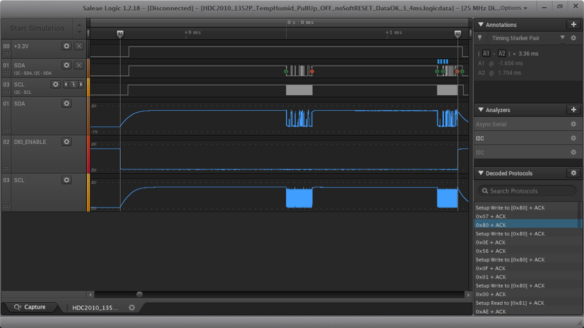
Figure 3-5 shows the SCE interaction with the HDC2010 sensor over the I2C bus, showing the positive pulse on Channel 0 (or 3.3 V) to the I2C pullups and the power on pulse (active low) for the HDC2010 device on Channel 2. The total time to start from power-off, configure the HDC2010 registers, and read out the sensor data is only 3.36 ms.
 Figure 3-5 Complete Initial SCE Access to HDC2010 (Power on of I2C Pullups, Configuration, Data Readout, and Power Off)
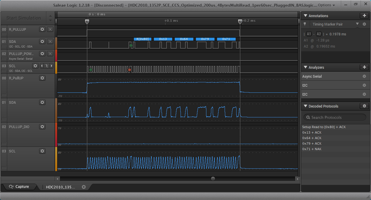
Note that all subsequent data readouts are shorter, if the HDC2010 sensor is not powered off every time but kept in standby between measurements. Both solutions were tested and the final firmware keeps the HDC2010 sensor in standby mode between measurements. This leads to a very fast sensor data readout with a duration of only 198 µs due to the multibyte read mode, as Figure 3-6 shows.
 Figure 3-6 Periodic Sensor Readout Using the SCE With 198 µs