SLAA913A January 2020 – June 2021
2.2 Hardware
For the measurements, the following hardware (available at TI.com) was used:
- CC1352P LaunchPad
- BOOSTXL-BASSENSORS (includes the HDC2010 sensor, the TMP116 sensor, and other sensors)
HW modifications: the I2C-bus pullup resistors on the CC1352P LaunchPad were removed as these are in parallel to the I2C pullup resistors found on BOOSTXL-BASSENSORS. The pullup resistors on the BoosterPack™ plug-in module are wired to a CC1352P DIO pin (extra wire); the existing copper trace to the +3.3V pin of the CC1352P LaunchPad was cut on the PCB. In this power-optimized design, the new wiring allows for powering the I2C pullup resistors only when data is transferred.
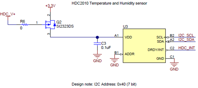
As the ADDR pin of the HDC2010 device in BOOSTXL-BASSENSOR is connected to GND, its slave i2C address is 0x40 (see Figure 2-1). The 0x40 address becomes 0x80 (Write) or 0x81 (Read) when used in the Sensor Controller Studio, which inserts the read/write bit as the last bit after the 7-bit address, as Table 2-1 shows.
| ADDR | ADDRESS (7-BIT ADDRESS) | BOOSTXL-BASSENSORS (8-BIT ADDRESS) |
|---|---|---|
| GND | 1000000 | 0x80(W)/0x81(R) |
| VDD | 1000001 | 0x82(W)/0x83(R) |
The HDC_V+ pin uses active low level voltage to control the P-MOSFET which gates the power to the HDC2010 sensor.
 Figure 2-1 Interfacing to HDC2010, Power Supply Line is
P-MOSFET Gated (Low Active)
Figure 2-1 Interfacing to HDC2010, Power Supply Line is
P-MOSFET Gated (Low Active)After power up, the HDC2010 device can be configured to a sampling frequency from one sample every two minutes down to five samples every second. The raw values provided by the HDC2010 sensor have to be calculated or converted into a human readable format for temperature and humidity, see Equation 1 and Equation 2.


Both of these equations are implemented in the Sensor Controller code example for demonstration purposes; however, the additional code reduces the available buffer memory for storing sensor data and negatively impacts the amount of data to be transmitted over-the-air.
For lowest power consumption, TI recommends to read and transmit the raw 16-bit humidity and 16-bit temperature sensor values over-the-air (after a packet with the desired payload length is created), while the conversion into a human readable format Equation 1 and Equation 2 can be done at the receiving or data display node.