SLAA951A August 2020 – September 2020 MSP430FR5041 , MSP430FR5043 , MSP430FR6005 , MSP430FR6007 , MSP430FR6041 , MSP430FR6043 , MSP430FR6045 , MSP430FR6047
1.2 EVM430-FR6043 Configuration
The transducer is connected to one of the transducer connectors with a jumper wire between the two positive transducer connectors (J5 pin 1 and J6 pin 1). The EVM is used with the standard gas meter software. The EVM schematics can be found here: TIDM-02003 Schematic.
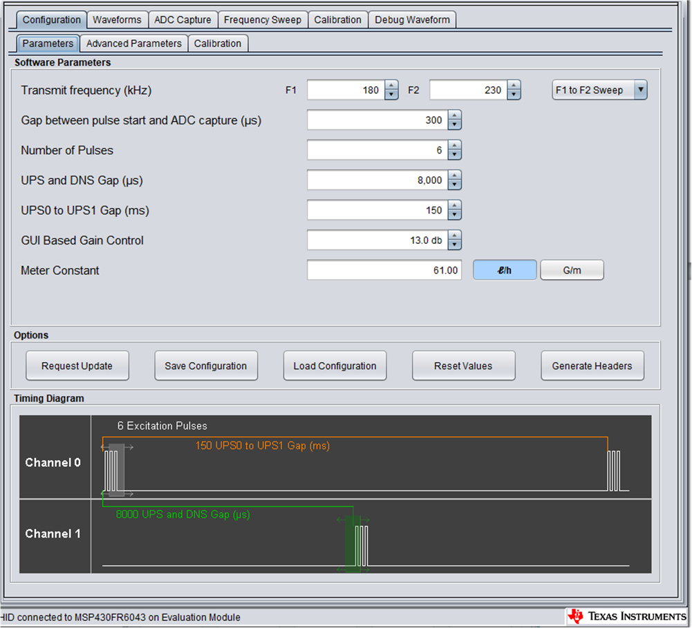
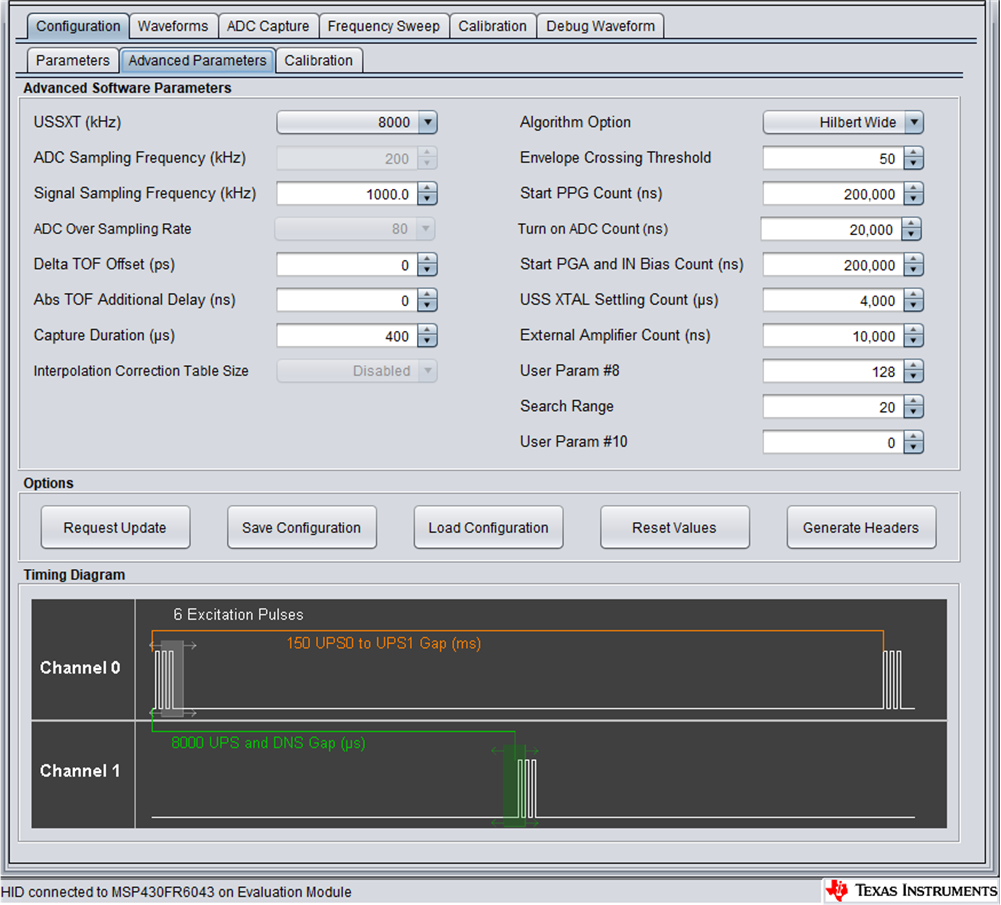
The Design Center GUI is used to configure the MSP430FR6043 and capture data.
The Design Center configuration used for testing can be seen in Figure 1-4 and Figure 1-5.
 Figure 1-4 Design Center Configuration
 Figure 1-5 Design Center Configuration (continued)