SLAA951A August 2020 – September 2020 MSP430FR5041 , MSP430FR5043 , MSP430FR6005 , MSP430FR6007 , MSP430FR6041 , MSP430FR6043 , MSP430FR6045 , MSP430FR6047
1.1 Transducer Placement
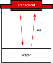
In order to obtain proper signal levels, the transducer should be placed as close as possible to the liquid level that is being sensed. Figure 1-3 depicts how the transducer is mounted with respect to the container and the water which is in it. The ultrasonic wave is reflected from the surface of the water and the roud trip time of flight is determined based on the correlation between the transmitted and received ultrasonic signals.
 Figure 1-3 Ultrasonic Configuration