SLAAE56A November 2022 – March 2023 MSPM0G1105 , MSPM0G1106 , MSPM0G1107 , MSPM0G1505 , MSPM0G1506 , MSPM0G1507 , MSPM0G3105 , MSPM0G3106 , MSPM0G3107 , MSPM0G3505 , MSPM0G3506 , MSPM0G3507 , MSPM0L1105 , MSPM0L1106 , MSPM0L1303 , MSPM0L1304 , MSPM0L1304-Q1 , MSPM0L1305 , MSPM0L1305-Q1 , MSPM0L1306 , MSPM0L1306-Q1 , MSPM0L1343 , MSPM0L1344 , MSPM0L1345 , MSPM0L1346
- Abstract
- Trademarks
- 1MSPM0 Portfolio Overview
- 2Ecosystem and Migration
- 3Core Architecture Comparison
- 4Digital Peripheral Comparison
- 5Analog Peripheral Comparison
- 6Revision History
2.5 Migration and Porting Example
To become more familiar with the TI ecosystem and explain how to best get started with MSPM0, this section describes the step-by-step migration process of a basic application.
To demonstrate the process of porting from STM32 to MSPM0, this description includes the steps to port a basic low-power UART monitor application from an STM32G0x to a MSPM0 device using an existing ST UART example as the starting point.
Step 1. Chose the right MSPM0 MCU
The first step of migration is to choose the correct MSPM0 device for the application. To do this, the portfolio section of this guide can be used to choose a MSPM0 family. To narrow down to a specific device using the product selection tool. STM32G0 and MSPM0 share the M0+ core, but features such as memory size, power, and key peripherals must also be considered. MSPM0 also offers many pin-to-pin scalable options, providing the ability to easily scale to larger or smaller memory devices without changing anything else in the system.
For purposes of this example, we have chosen the MSPM0G3507 as the best fit for his application.
Step 2. Select hardware and order an EVM
Using an evaluation module (EVM) can expedite the migration process. For the MSPM0 MCUs, a LaunchPad kit is the easiest hardware to begin on. LaunchPad kits are easy to use because they come with a built-in programmer and are designed to enable rapid development.
The MSPM0G3507 has a LaunchPad development kit (LP-MSPM0G3507) that can be used for porting the software.
Step 3. Setup software IDE and SDK
Before the software can be ported, a software development environment must be chosen and setup. GUID-3F8D0EDE-3C40-4970-BA06-C78FB1EBDE6C.html shows all of the IDEs supported by MSPM0. The migration and porting process is similar for any IDE that is chosen. The latest version of the MSPM0 SDK should be used.
For this example, TI's CCS is the chosen IDE.
 Figure 2-5 Code Composer Studio IDE
Step 4. Software porting
When the environment is ready, start using the MSPM0 SDK. As mentioned, the MSPM0 SDK is similar to the STM32Cube software package. The MSPM0 SDK offers different layers for software development. MSPM0 TI Drivers operate at a similar level to STM32Cube HAL, while MSPM0 DriverLib is comparable to the STM32Cube low-level drivers. Most MSPM0 users find DriverLib level software is the best fit for their applications, so most MSPM0 software examples are also DriverLib based. This example uses DriverLib.
One option when porting a project is to try to replace each section of code with equivalent MSPM0 DriverLib APIs, but this is not generally the easiest path. Generally, it is best to first understand the application code being ported. Then start with the closest MSPM0 example project and modify it to match the original code functionality. This process is going to be shown below using a low-power UART example from STM32CubeG0. For more complex projects using many peripherals, this process is typically repeated for each peripheral.
Step 4a: Understand the application
The following description is from the example project from STM32CubeG0 named 'LPUART_WakeUpFromStop_Init'.
@par Example Description

Configuration of GPIO and LPUART peripherals to allow characters received on LPUART_RX pin to wake up the MCU from low-power mode. This example is based on the LPUART LL API. The peripheral initialization uses LL initialization function to demonstrate LL init usage.

LPUART Peripheral is configured in asynchronous mode (9600 bauds, 8 data bit, 1 start bit, 1 stop bit, no parity).
No HW flow control is used.
LPUART Clock is based on HSI.

Example execution:
After startup from reset and system configuration, LED3 is blinking quickly during 3 sec, then MCU enters "Stop 0" mode (LED3 off). On first character reception by the LPUART from PC Com port (ex: using HyperTerminal) after "Stop 0" Mode period, MCU wakes up from "Stop 0" Mode.

Received character value is checked :
- On a specific value ('S' or 's'), LED3 is turned On and program ends.
- If different from 'S' or 's', program performs a quick LED3 blinks during 3   sec and enters again "Stop 0" mode, waiting for next character to wake up.
The first step is to understand the main settings for the MCU. This is generally clock speeds and power policies. In this example, the general clock frequency is not specified because the only important setting is that the UART works in low power Stop0 mode. It states the low power UART clock is based on the 'HIS' or high-speed internal oscillator meaning there is no external crystal being used. The UART runs at 9600 baud, 8 data bits, 1 start and stop bit, no parity. No hardware flow control is used. The application side checks for an 'S' or 's' to be received and blinks an LED.
Step 4b: Find the closest MSPM0 example
Next step is to understand any differences between the UART modules for STM32G0 and MSPM0 and then find the closest example in the MSPM0 SDK. This is easily accomplished by referring to the UART section in GUID-681A24B4-4C42-40B6-B661-452E41A82D83.html. This section highlights differences between the UART modules and links to the UART-related MSPM0 SDK code examples. The closest example in the SDK for this example is probably uart_echo_interrupts_standby where the "UART RX/TX echos using interrupts while device is in STANDBY mode".
This MSPM0 example is similar, but not identical to the being ported. This example is going to standby mode, which is a lower power mode than Stop mode. The UART communication settings must be checked as well as which GPIOs are being used. Finally, the application layer of monitoring for a specific character must be added.
Step 4c: Import and modify the example
Once a similar example is found, Open CCS and import the code example by going to Project > Import CCS Projects... and navigate it to the MSPM0 SDK example folder. Import the example. Here is the uart_echo_interrupts_standby example imported. This is a SysConfig project, so the main C file is simple. It first calls the SysConfig driverlib initialization which is a function autogenerated by SysConfig to configures the device. Then it enables the UART interrupt. Finally it goes to sleep waiting for any UART transaction. If it receives a UART transaction, it echos the data right back and wakes up.
 Figure 2-6 uart_echo_interrupts_standby Example
To see the SysConfig configuration, open the .syscfg file, which opens on the SYSCTL tab by default. For detailed guide on using SysConfig, see the SysConfig Guide in the in the MSPM0 SDK.
The first thing to note is the power policy. This MSPM0 example is using Standby0 mode but the goal is to use Stop0 mode. By clicking the drop-down list, the correct low-power mode can be chosen. All of the clocks and oscillators can be configured on this tab as well, but are fine for now.
 Figure 2-7 Power Mode Configuration
Next, check the UART communication settings on the UART tab (see #GUID-24939E4D-F455-443D-B43A-FE2EC712B69D). In this case, the baud rate is already set to 9600 and the rest of communication settings are correct. The receive interrupt is already enabled and used in the main program. Also check the UART module and pins being used by clicking the chip icon in the top right and checking the highlighted pins for the UART. Nothing here needs to be changed as these are already connected to the MSPM0G3507 LaunchPad kit's backchannel UART.
 Figure 2-8 UART Configuration
This example currently has no GPIOs configured for driving an LED, but the configuration can be added easily (see #GUID-0C809667-F22A-4F0C-B83C-77A7372385D7). A GPIO can be added by using the +ADD button at the top of the page. The GPIO port and pin can be named, in this case 'LED' and 'RED' respectively. This GPIO is set as an output and then put on Port A pin 0 (PA0.) On the LaunchPad kit, this GPIO is tied to a simple red LED.
 Figure 2-9 GPIO Configuration
When the project is saved and rebuilt, SysConfig updates the ti_msp_dl_config.c and ti_msp_dl_config.h files for the example. At this point, the example hardware configuration has been modified to match the full functionality of the original software being ported. The only remaining effort is application-level software to check the incoming UART bytes and toggle the LED. This is accomplished by moving over a small amount of code into the main C file.
 Figure 2-10 Changes to Application Code
Two changes are made to the application code. First, DL_SYSCTL_disablesSleepOnExit() is used so that the MSPM0 wakes briefly on each UART RX. Next, a simple check of the UART RX data is added, and if an 'S' or 's' is received, the red LED is turned on. Anything else and it is turned off.
Step 5: Debug and verify
The following figures are captures from an logic analyzer showing the UART communication at 9600 baud and the red LED being turned on and off correctly. The code is echoing every UART character but only turning on the LED when the correct character is received.
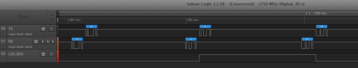 Figure 2-11
 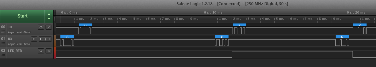 Figure 2-12
 The software has successfully been ported! If this was just the first peripheral of many, continue to repeat this process and use SysConfig to combine each block.