SLAAE88B December 2022 – March 2024 MSPM0G1105 , MSPM0G1106 , MSPM0G1107 , MSPM0G1505 , MSPM0G1506 , MSPM0G1507 , MSPM0G3105 , MSPM0G3106 , MSPM0G3107 , MSPM0G3505 , MSPM0G3506 , MSPM0G3507 , MSPM0L1105 , MSPM0L1106 , MSPM0L1303 , MSPM0L1304 , MSPM0L1304-Q1 , MSPM0L1305 , MSPM0L1305-Q1 , MSPM0L1306 , MSPM0L1306-Q1 , MSPM0L1343 , MSPM0L1344 , MSPM0L1345 , MSPM0L1346
3.2.2 Steps to Using the GUI
- Connect the target device and the
XDS110 to the PC. When using the XDS110 integrated in the LaunchPad kit, connect the
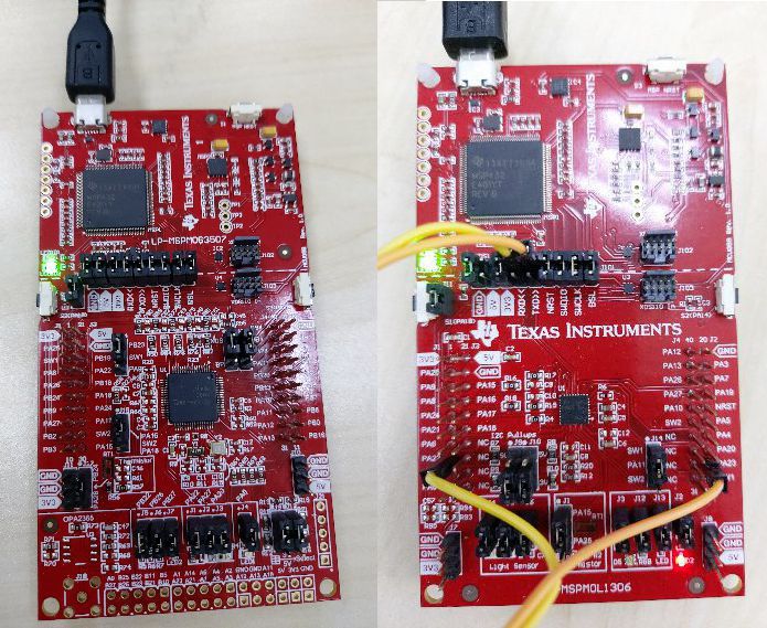
micro USB cable to the PC as Figure 3-7.
The ROM-based BSL UART pins for MSPM0G3507 are PA10 and PA11, and the pins are directly connected to the XDS110 backchannel UART, so all of the jumpers in J101 are required (see Table 3-4).
On the LP-MSPM0L1306, the XDS110 backchannel UART pins are different from the BSL UART pins, so disconnect TXD and RXD in J101 and use jumper wires to connect PA22 and PA23 (see Table 3-4).
 Figure 3-7 LaunchPad Kit Connection
(Left: LP-MSPM0G3507, Right: LP-MSPM0L1306)Table 3-3 Jumpers Connection
Figure 3-7 LaunchPad Kit Connection
(Left: LP-MSPM0G3507, Right: LP-MSPM0L1306)Table 3-3 Jumpers ConnectionBoards Mode Jumpers Need Populated Jumpers Need Unpopulated LP-MSPM0G3507 Target J101 (power, UART pins, Reset and BSL invoke pin), J4, J7(LED), J21, J22 (UART to J101 XDS) NA LP-MSPM0L1306 Target J101 (GND, 3V3, NRST, BSL), J2, J3(LED) J101 (TXD, RXD) For standalone XDS110, the auxiliary interface (AUX) uses the signal connections in Table 3-4.
Table 3-4 Standalone Signal ConnectionSignal Standalone XDS110 Target Device Signal AUX Port Signal LP-MSPM0G3507 LP-MSPM0L1306 NRST IO output IOOUT0 NRST NRST pin NRST pin Invoke IO output IOOUT1 Default: Invoke pin PA18 PA18 UART RXD UARTRX TXD PA10/UART0_TX PA23/UART0_TX TXD UARTTX RXD PA11/UART0_RX PA22/UART0_RX - Use the GUI to download the image to
the target.
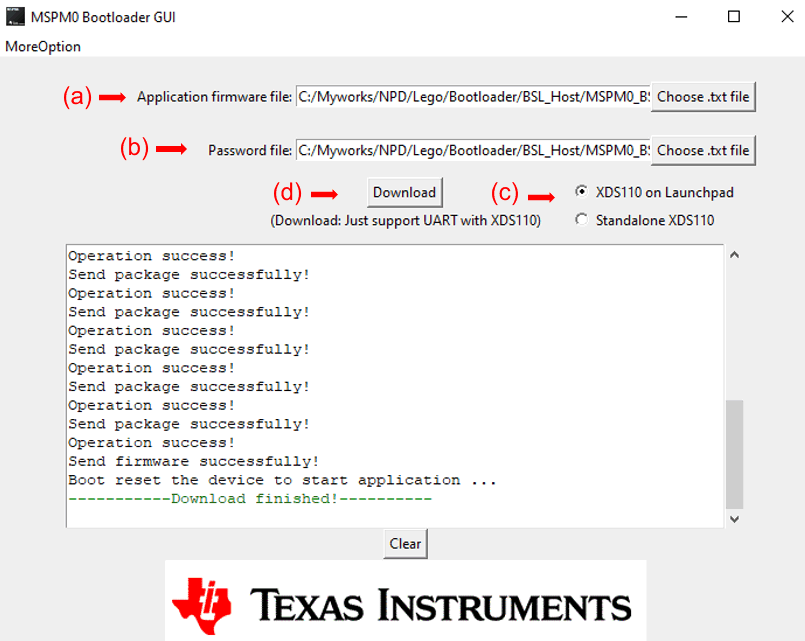
- Choose the TI-TXT format image file that need to be downloaded. (There are two demo images in the folder named input)
- Choose the TI-TXT format password file (a default file is in the input folder). For details on preparing this file, see Section 3.2.1.
- Choose hardware bridge.
- Click the download button.
The GUI automatically invokes the BSL so there is no need to manually invoke the BSL during this operation.
 Figure 3-8 Steps to Download Image by
GUI With UART
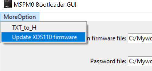
 - If using the XDS110, this GUI
supports XDS110 firmware version firmware_3.0.0.20 or higher. If errors occur when
download the image, update the XDS110 firmware.
 Figure 3-9 Update XDS110
Firmware