SLAU546A March   2014  – October 2021 TRF37A73 , TRF37A75 , TRF37B73 , TRF37B75 , TRF37C73 , TRF37C75 , TRF37D73
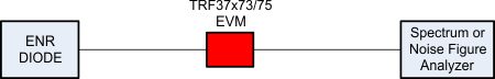
 

  1. 1Contents
  2. 2EVM Overview
    1. 2.1 Schematic and BOM
    2. 2.2 TRF37x73/75 EVM Bill of Material
    3. 2.3 General Usage Information
  3. 3EVM Layout
    1. 3.1 Description: Stack up and Material
    2. 3.2 PCB Layers
  4. 4EVM Board Loss
  5. 5Test Block Diagrams
    1. 5.1 Noise Figure
    2. 5.2 Gain and P1dB
    3. 5.3 OIP3
  6. 6Revision History

Noise Figure

Recommendations and comments:

  1. Use the traditional Y-factor method
  2. Take into account losses of coax to the EVM board
  3. Take into account losses of traces on the board up to the input pin of the device under test (DUT)
GUID-075A0009-EBCC-426D-AEE5-D3B533CB8D75-low.gif