SLAU776A May 2018 – December 2023 ADC12DL2500 , ADC12DL3200
- 1
- Abstract
- Trademarks
- 1Introduction
- 2Equipment
-
3Setup Procedure
- 3.1 Install the High Speed Data Converter (HSDC) Pro Software
- 3.2 Install the Configuration GUI Software
- 3.3 Connect the EVM and TSW14DL3200EVM
- 3.4 Connect the Power Supplies to the Boards (Power Off)
- 3.5 Connect the Signal Generators to the EVM (*RF Outputs Disabled Until Directed)
- 3.6 Turn On the TSW14DL3200EVM Power and Connect to the PC
- 3.7 Turn On the ADC12DLXX00EVM 5-V Power Supply and Connect to the PC
- 3.8 Turn On the Signal Generator RF Outputs
- 3.9 Open the ADC12DLXX00EVM GUI and Program the ADC and Clocks
- 3.10 Calibrate the ADC Device on the EVM
- 3.11 Open the HSDC Software and Load the FPGA Image to the TSW14DL3200EVM
- 3.12 Capture Data Using the HSDC Pro Software
- 4Device Configuration
- A Troubleshooting the ADC12DL3200EVM
- B Optional ADC12DL3200EVM Configurations
- C Revision History
3.9 Open the ADC12DLXX00EVM GUI and Program the ADC and Clocks
The device configuration GUI is installed separately from the HSDC Pro installation and is a stand-alone GUI.
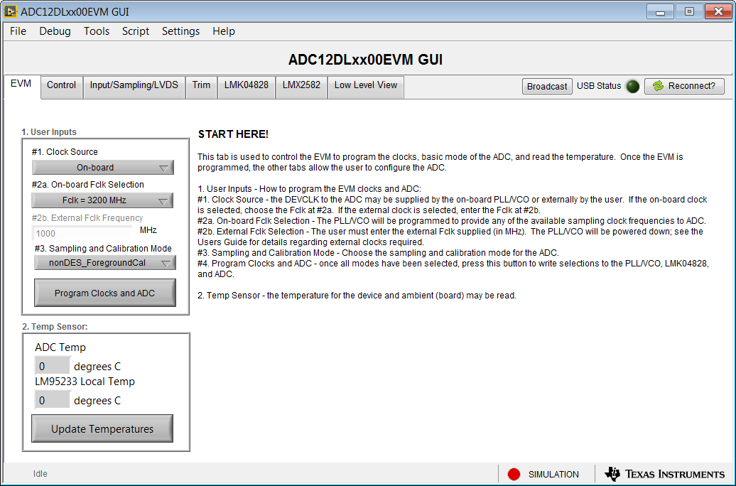
Figure 3-2 shows the GUI open to the EVM tab. Tabs at the top of the panel organize the configuration into device and EVM features, with user-friendly controls and a low-level tab for directly configuring the registers. The EVM has three configurable devices: the ADC12DLXX00, LMK04828, and LMX2582. The register map for each device is provided in the device data sheets.
 Figure 3-2 Configuration GUI: EVM Tab
- Open the ADC12DLxx00EVM GUI.
- Select the onboard clock as the clock source.
- If using ADC12DL3200 evm variant select Fs/Fclk = 3200 MHz as the onboard Fs/Fclk. If using ADC12DL2500 evm variant set Fs/Fclk to 2500 MHz selection.
- Select nonDES_ForegroundCal operating mode.
- Click Program Clocks and ADC. This action overwrites any previous device register settings.