SLAU902A September 2023 – January 2024
- 1
- Description
- Get Started
- Features
- Applications
- 6
- 1Evaluation Module Overview
-
2Hardware
- 2.1 Setup
- 2.2 AC-MB Settings
- 2.3
TAx5x12EVM-K Hardware Settings
- 2.3.1 TAx5x12 EVM Input Hardware Settings
- 2.3.2 TAx5x12 EVM Output Hardware Settings
- 2.3.3 TAx5x12 Headset Connection
- 2.3.4 GPIO1 Hardware Configurations
- 2.3.5 GPIO2 Hardware Configurations
- 2.3.6 GPI1 Hardware Configurations
- 2.3.7 GPO1 Hardware Configurations
- 2.3.8 I2C Address Hardware Configurations
- 2.3.9 Audio Serial Interface Hardware Configurations
-
3Software
- 3.1 Software Description
- 3.2 PurePath Console 3 Installation
- 3.3
TAx5x12 EVM GUI
- 3.3.1 Software Overview
- 3.3.2 Configuration View
- 3.3.3 End System Integration View
- 3.3.4 Register Map View
- 3.3.5 Preset Configuration
- 3.3.6 I2C Monitor View
- 3.4 Configuration Examples
- 3.5 System Overview
- 4Hardware Design Files
- 5Additional Information
- 6References
- 7Revision History
3.3.6 I2C Monitor View
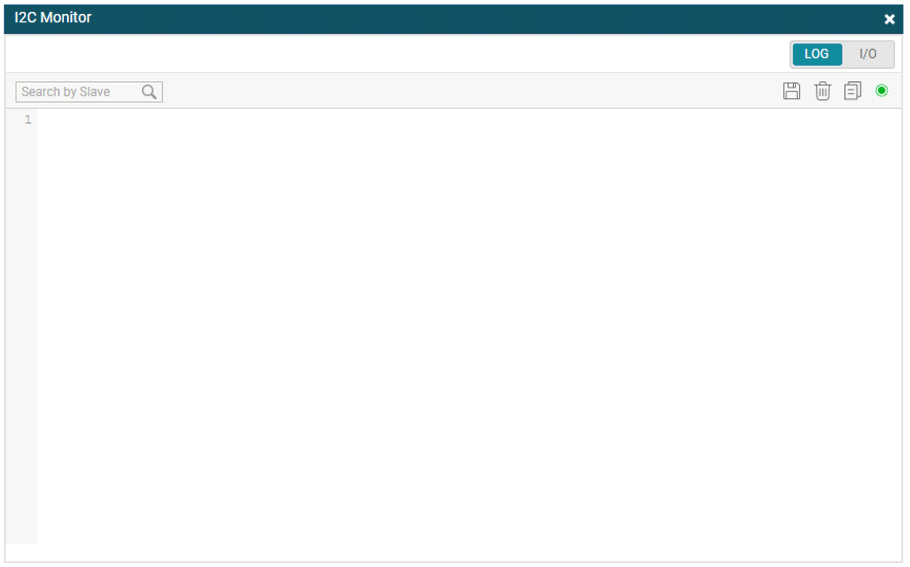
The I2C Monitor tab allows users to load existing device configuration files or direct I2C transactions to the device registers. To access this window panel, click on the I2C Monitor button at the bottom of the GUI. The I2C monitor window opens as shown in the figure below. The LOG screen allows users to log or record any I2C transaction. This is useful for when users want to record device register to use at later time; users can click on the green LED button once and the button turns red for recording. To stop recording, click the red LED button once and the button turns back to green.
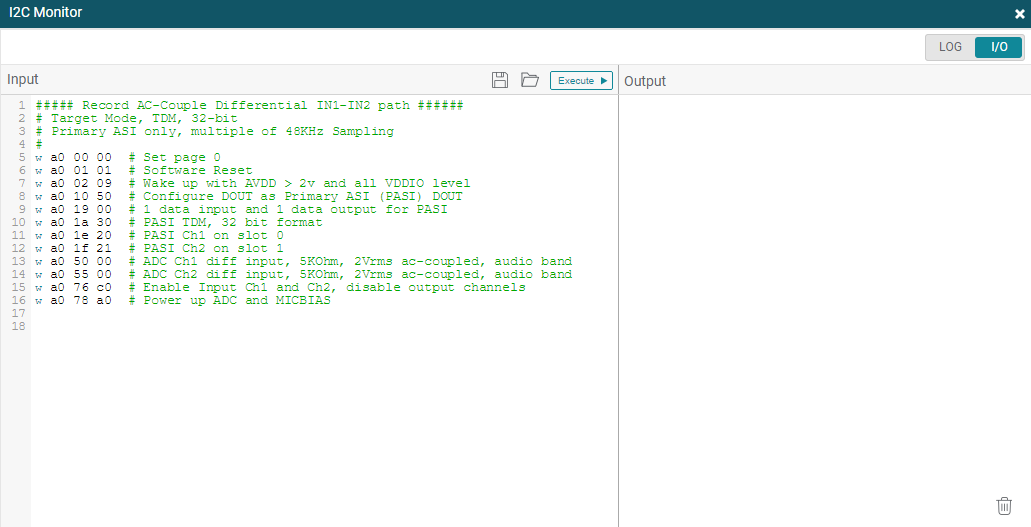
To load an existing file or to manually write or read I2C transaction, click on the I/O button to open the input/output window.
 Figure 3-31 I2C Monitor Window
 Figure 3-32 I2C Monitor I/O Window