SLAU903 October 2023
- 1
- Description
- Get Started
- Features
- Applications
- 6
- 1Evaluation Module Overview
- 2Hardware
-
3Software
- 3.1 Software Description
- 3.2 PurePath Console 3 Installation
- 3.3 TAx5x1x-Q1 EVM GUI
- 3.4 Configuration Examples
- 3.5 System Overview
- 4Hardware Design Files
- 5Additional Information
- 6References
2.3.1 TAx5412-Q1 EVM Input Hardware Settings
The TAx5412-Q1 evaluation module has several input configuration options. The EVM allows the user to evaluate the device across multiple operation modes. The different operation modes are highlighted in this section.
 Figure 2-8 TAC5412Q1/TAC5312Q1/TAA5412Q1 EVM Input Architecture for Channel 1 and 2
The IN1 and IN2 input architecture allows these two channels to be quickly configured to support any of the supported operation modes. The INxP and INxM pins of the TAx5412-Q1 can optionally connect to onboard microphones for quick evaluation of a microphone in AC- or DC-coupled modes. Jumper configuration details can be found in Figure 3-9.
For TAC5x11-Q1 evaluation module, The DIN1P and DIN1M can be connected to IN1P and IN1M respectively through jumper J52 and J53 as shown in Figure 3-8. Only IN1 Input Terminal is applicable in this evaluation module from the configuration table.
 Figure 2-9 TAC5311-Q1 EVM Input Architecture for Channel 1 and DIN1P/M
| Input Terminal | Input Mode | Installed Jumpers | Uninstalled Jumpers | Input Swing | Topology |
Register |
|---|---|---|---|---|---|---|
IN1 | LINE-IN Differential, AC-coupled | J8, J20, J21 | J4, J5, J6, J11, J12, J15, J16 | 10 VRMS | 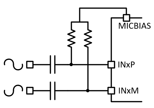 | B0_P0_R80, B0_P1_R115 |
LINE-IN Single-ended, AC-coupled | J6, J8, J12 (2-3), J20, J21 | J4, J5, J11, J15, J16 | 5 VRMS | 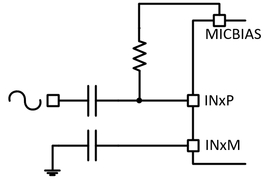 | B0_P0_R80, B0_P1_R115 | |
| LINE-IN Differential, DC-coupled | J15, J16 | J4, J5, J6, J11, J12, J20, J21, J8 (DUT MICBIAS is not used) | 10 VRMS | 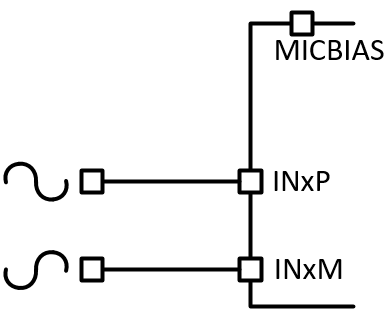 | B0_P0_R80 | |
| LINE-IN Single-ended, DC-coupled | J6, J12 (2-3), J15, J16 | J4, J5, J11, J20, J21, J8 (DUT MICBIAS is not used) | 5 VRMS | 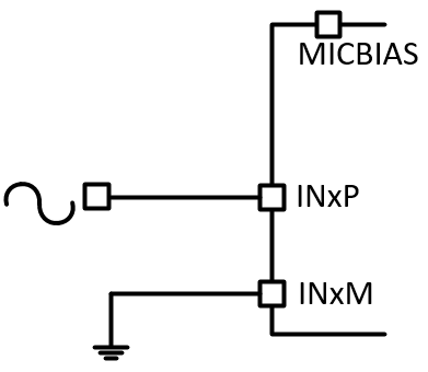 | B0_P0_R80 | |
| On-board Electret Condenser Microphone (ECM) Differential, AC-coupled | J4, J5, J8, J11, J12 (1-2), J20, J21 | J6, J15, J16 | Refer to Microphone data sheet | 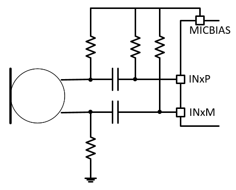 | B0_P0_R80, B0_P1_R115 | |
| On-board Electret Condenser Microphone (ECM) Single-ended, AC-coupled | J4, J5, J8, J11, J12 (2-3), J20 | J6, J15, J16, J21 | Refer to Microphone data sheet | 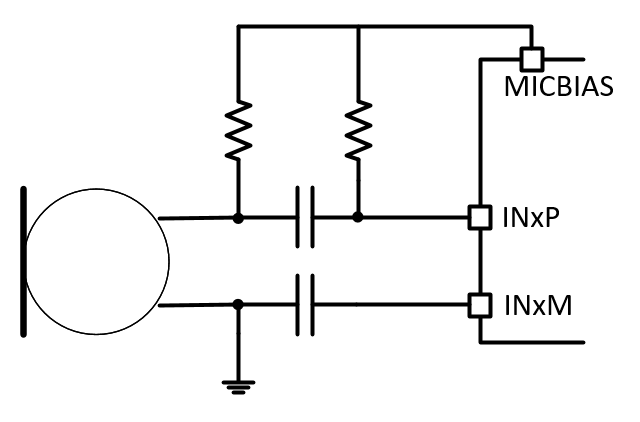 | B0_P0_R80, B0_P1_R115 | |
| On-board Electret Condenser Microphone (ECM) Differential, DC-coupled | J4, J5, J8, J11, J12 (1-2), J15, J16 | J6, J20, J21 | Refer to Microphone data sheet | 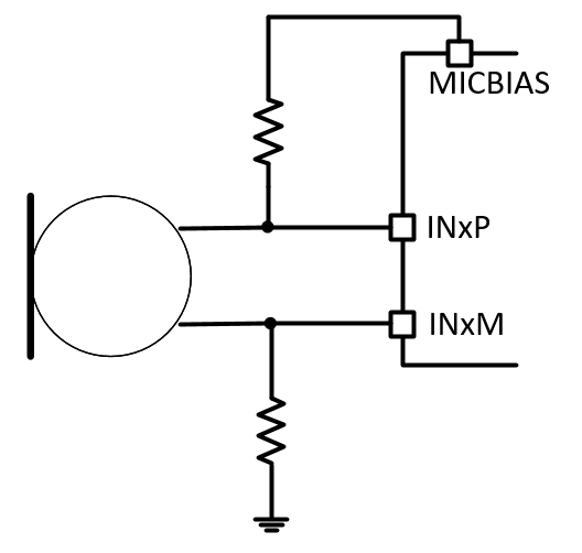 | B0_P0_R80, B0_P1_R115 | |
| On-board Electret Condenser Microphone (ECM) Single-ended, DC-coupled | J4, J5, J8, J11, J12 (2-3), J15, J16 | J6, J20, J21 | Refer to Microphone data sheet | 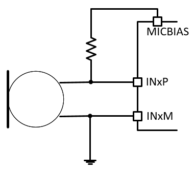 | B0_P0_R80, B0_P1_R115 | |
| IN2 | LINE-IN Differential, AC-coupled | J8, J22, J23 | J7, J9, J13, J14, J17, J18, J46 | 10 VRMS | | B0_P0_R85, B0_P1_R115 |
| LINE-IN Single-ended, AC-coupled | J7, J8, J14 (2-3), J22, J23 | J9, J13, J17, J18, J46 | 5 VRMS | | B0_P0_R85, B0_P1_R115 | |
| LINE-IN Differential, DC-coupled | J17, J18 | J7, J9, J13, J14, J22, J23, J46, J8 (DUT MICBIAS is not used) | 10 VRMS | | B0_P0_R85 | |
| LINE-IN Single-ended, DC-coupled | J7, J14 (2-3), J17, J18 | J9, J13, J22, J23, J46, J8 (DUT MICBIAS is not used) | 5 VRMS | | B0_P0_R85 | |
| On-board Analog MEMS microphone, AC-coupled | J8, J9, J22, J23, J46 | J7, J13, J14, J17, J18 | Refer to Microphone data sheet | 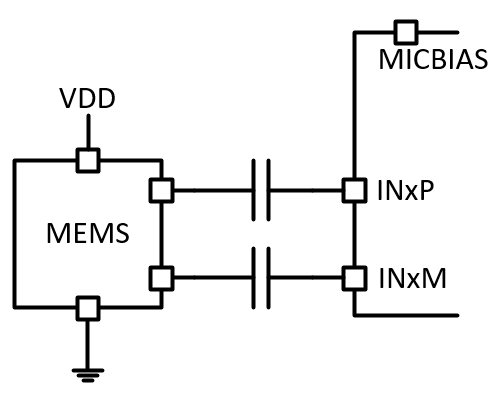 | B0_P0_R85, B0_P1_R115 | |
| On-board Analog MEMS microphone, DC-coupled | J9, J17, J18, J46 | J7, J13, J14, J22, J23, J8 (DUT MICBIAS is not used) | Refer to Microphone data sheet | 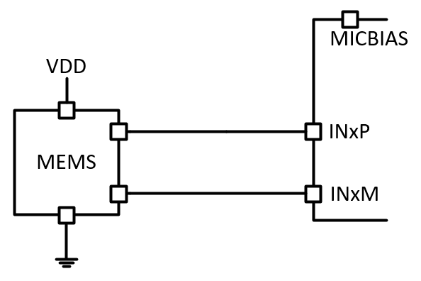 | B0_P0_R85, B0_P1_R115 |