SLDU019B December 2015 – March 2016
2.2.2 Programming the PGA450-Q1 EEPROM
The PGA450Q1EVM-S is preloaded with the EEPROM values listed in Table 2. These instructions are provided in the event that the user prefers to modify the EEPROM using the PGA450Q1EVM GUI, rather than the corresponding UART command. Use the steps that follow to program the device for EEPROM memory.
- Assuming the MCU status is still set to MICRO IS IN RESET, go to the EEPROM tab, and enter the register values for addresses 0x00 through 0x1F as listed in Table 3.
- Click the WRITE SELECTED button. To ensure the threshold values are written correctly, click the READ ALL button.
- Click the PROGRAM EEPROM button to store the threshold values.
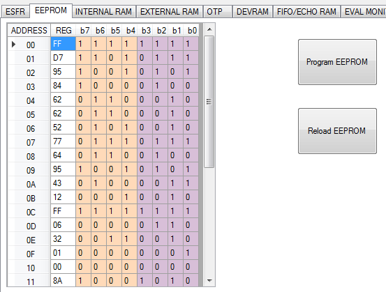
- Click the Reload button. To ensure the threshold values have been written correctly and retained, click the READ ALL button. The EEPROM table should appear as shown in Figure 3.
The values at 0x00 to 0x1F are the threshold values used in software. TI recommends that the user begins with the example values provided, and then adjusts these values later as necessary.
The value at address 0x1F is the sensor address.
Table 3. EEPROM Register Map Values
| Register Address | Register Value | Description |
|---|---|---|
| 0x00 | 0xFF | Threshold level 0 |
| 0x01 | 0xD7 | Threshold level 1 |
| 0x02 | 0x95 | Threshold level 2 |
| 0x03 | 0x84 | Threshold level 3 |
| 0x04 | 0x62 | Threshold level 4 |
| 0x05 | 0x62 | Threshold level 5 |
| 0x06 | 0x52 | Threshold level 6 |
| 0x07 | 0x78 | Where in FIFO to apply threshold level 7 defined at EEPROM address 0x08 from to the end of the FIFO. Long mode (most significant hex) multiplied by 40 [interval 40 to 600]. Short mode (least significant hex) multiplied by 8 [interval 8 to 120]. |
| 0x08 | 0x64 | Threshold level 7, the fixed level of threshold to end of FIFO. Long mode and short mode multiplied by 5 and 1 respectively. |
| 0x09 | 0x95 | Threshold ignore count from beginning of FIFO for long (most significant hex) and short (least significant hex) modes respectively. |
| 0x0A | 0x43 | 1-6 change interval of the threshold level across FIFO for long mode (most significant hex) multiplied by 8 [interval 8 to 120]. Short mode (least significant hex) multiplied by 2 [interval 2 to 15]. |
| 0x0B | 0x12 | PULSE_CNTA |
| 0x0C | 0xFF | BLANKING_TIMER |
| 0x0D | 0x06 | FIFO_CTRL |
| 0x0E | 0x32 | DOWNSAMPLE |
| 0x0F | 0x01 | CONTROL_1 |
| 0x10 | 0x00 | BURST_MODE |
| 0x11 | 0x8A | BURST_ONA_LSB |
| 0x12 | 0x8A | BURST_OFFA_LSB |
| 0x13 | 0x05 | DEADTIME |
| 0x14 | 0x09 | SAT_DEGLITCH |
| 0x15 | 0x03 | BPF_B1_MSB |
| 0x16 | 0x2D | BPF_B1_LSB |
| 0x17 | 0xEC | BPF_A2_MSB |
| 0x18 | 0x3D | BPF_A2_LSB |
| 0x19 | 0xF9 | BPF_A3_MSB |
| 0x1A | 0xA5 | BPF_A3_LSB |
| 0x1B | 0x35 | LPF_B1_MSB |
| 0x1C | 0xDD | LPF_B1_LSB |
| 0x1D | 0x14 | LPF_A2_MSB |
| 0x1E | 0x46 | LPF_A2_LSB |
| 0x1F | 0x01 | Sensor address |

1. The Program EEPROM button programs the EEPROM cache into the EEPROM memory. The values displayed in the GUI are transferred to the cache before being programmed.
2. The Reload EEPROM button copies the EEPROM memory into the EEPROM cache. The values in the GUI are then updated.
Figure 3. EEPROM Registers Programmed Correctly