SLLA623 September 2023 THVD8000 , THVD8010
3 Powerbus vs. Classical RS-485
How is Powerbus different from Classical RS-485? With the same bus facing architecture as a standard RS-485 device with similar electrical characteristics Powerbus and Classical RS-485 share many of the same features. However, even with a large degree of similarity between the standards they are unable to communicate with one another. This section will guide the end user on how to navigate the similarity and differences between these similar types of devices.
 Figure 3-1 Powerbus Standard
Pinout
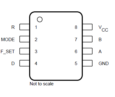
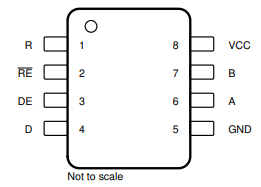
 Figure 3-2 Standard Pinout for 8-Pin Half
Duplex RS-485 Transceivers
Figure 3-2 Standard Pinout for 8-Pin Half
Duplex RS-485 TransceiversSince both Classical RS-485 and Powerbus share a similar bus facing architecture as well as a similar controller facing architecture the standards will have a few commonalities. When looking at the controller side pins there are two pins that function equivalently between the two standards – that being the “D” and “R” pins. R sends single ended data signals to the controller when the receiver is active and high-z otherwise. While D transmits single ended data onto the differential bus. Standard VIH (min) is 2V and VIL (max) is 0.8V between Most Classical RS-485 and Powerbus.
The mode pin on the THVD8000 is equivalent to the /RE and DE pins if they are shorted together. A logic low of MODE = THVD80X0 in RX Mode and a logic high on MODE = THVD80X0 in TX Mode. All of these pins allow the controller to determine the flow of data either coming to the controller or flowing away from the controller. The key distinction being that the THVD80X0 does not have a true disabled state due the MODE pin only allowing for 2 distinct but active modes – whereas Classical RS-485 with enables will allow for shutdown/disabled mode of the device with an active VCC level. It should be noted that the enables are not explicitly defined in RS-485 standard, but are a very common aspect of many RS-485 devices and the Powerbus family is using a less standard method of control to allow for additional functionality in that of the F_SET pin. The F_SET pin is used to set modulation frequency with a resistor to ground – to keep Powerbus in a typical 8-pin package common to RS-485 the control pins had to be moved into a single control pin.
The similarities do not end with the console facing pins. The power pins are equivalent, but more interestingly – so are bus facing pins. The bus interface will conform to all of the RS-485 required specs except for 1 – which is the differential input thresholds. Powerbus devices have the same drive strength, loading as a 1/8 unit load device, common mode input voltage range, and short circuit current limit to name a few key specifications. Ultimately what this means is that the THVD80X0 line of devices, if placed onto a standard RS-485 bus will not cause damage and not receiver damage under normal operating conditions. Due to Powerbus’s inability to disable the transceiver without cutting power to the device external methods of separation may need to be utilized if working with both types of devices on a board.
As previously mentioned the one specification that Powerbus is not aligned with for RS-485 are the input thresholds. This is largely due to the modulation scheme implemented by the THVD80X0 line of devices. In Classical RS-485 -200mV and less is a logic low and 200mV or higher is a logic high – this is the base line for input thresholds. Powerbus devices can’t use this logic as a logic high is ideally 0V and a logic low is going to alternate between positive and negative values. What this means is that for older RS-485 systems without integrated fail-safes if the THVD8000 sends a logic 1 it will be read as undefined by the Classical RS-485 device. If the RS-485 system is using modern transceivers with integrated fail-safes then a logic 1 will actually be read as a 1 as 0 V are read as logic one on more modern devices. However, on older and modern RS-485 transceivers if a logic 0 is sent from the THVD8000 the Classical RS-485 transceiver will read that as an alternating bit pattern with a data rate of 2 × Modulation frequency. Assuming that the transceiver is rated for the higher data-rate, the data read will not be correct. If this though experiment is flipped to where the THVD80X0 device is receiving data – the THVD80X0 family of devices looks at signal magnitude and it also passes the signal through a bandpass filter – so the data signal will either look like a solid string of 0’s or like nothing is being transmitted at all due to the signal being rejected by the internal bandpass filter. It can be thought that Powerbus devices and Classical RS-485, while very similar, do not speak the same language and can’t be used to communicate to one another.