SLLU325 July 2020 – MONTH
7 EVM Schematics and Layout
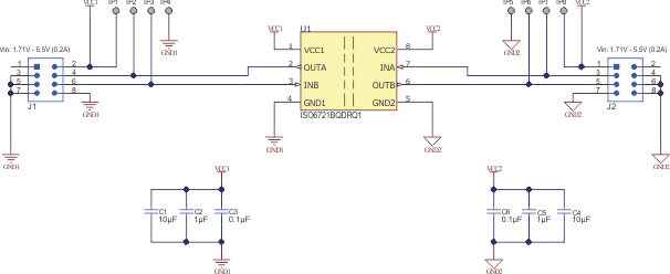
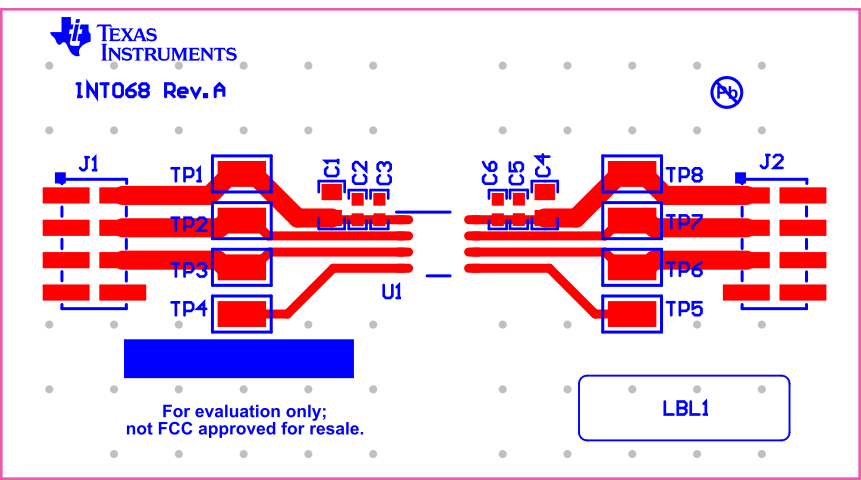
The ISO6721DEVM is designed to accommodate any of the ISO672x dual-channel devices in an 8-pin package. To evaluate any of the ISO672x dual-channel devices in an 8-pin package, replace ISO672x with the device of interest on the ISO6721DEVM PCB. No other component requires any modification. Figure 7-1 shows the ISO672x EVM schematic and Figure 7-2 shows the printed-circuit board (PCB) layout.
 Figure 7-1 ISO6721DEVM EVM Schematic
 Figure 7-2 PCB Layout