SLOA293A September 2020 – October 2021 DRV8424 , DRV8426 , DRV8428 , DRV8434 , DRV8434A , DRV8434S , DRV8436 , DRV8436E , DRV8889-Q1
2.2.1 Stepper Driver Channel-to-Channel Current Matching
A stepper motor driver has two electrical current windings and each winding is typically controlled with an H-Bridge. As Figure 2-1 shows, the stepper motor driver applies current waveforms approximating a sine wave into one coil (IA = coil A current) and a cosine wave into the other coil (IB = coil B current).
 Figure 2-1 Stepper Motor Coil Current
Waveform
Figure 2-1 Stepper Motor Coil Current
WaveformThe output torque and angular position of a stepper motor are controlled by the magnitude of the currents flowing thorough the two windings. The output current of a stepper motor driver can be expressed as:
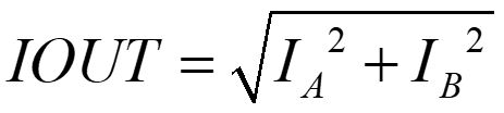
The angular position can be expressed as:
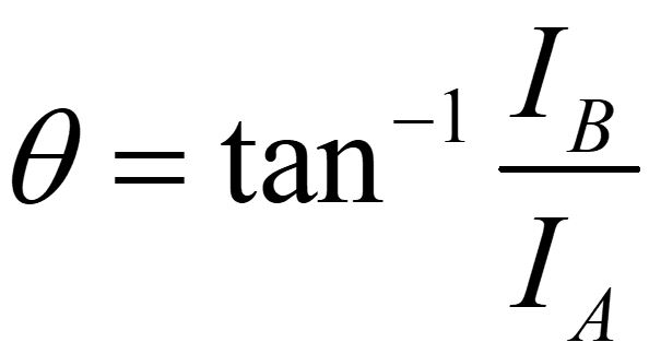
To ensure that the output current is constant and the incremental angle is the same in each microstep, ideally one coil current should be a pure sine wave, and the other coil current should be a pure cosine wave, phase-shifted by 90° from the other. The two coil currents must maintain this relation as much as possible, and any mismatch from ideal values will cause non-uniformity in the angular position increments and will lead to uneven output torque. The motor will step by a different amount of angle at each microstep, leading to position inaccuracies. Also, at higher speeds, the inaccuracies can cause short-term speed variations within a single rotation of the motor, which can lead to an increase in motor vibration.
As an example, assume a situation where IA and IB are both 1 A, such that the expected electrical angle of the stepper motor is 45° and the expected output current is 1.414 A. If the coil B current deviates by +5% from the expected value, the angle becomes 46.4° instead, which is 3% higher than the expected value and might be enough to distort the quality of image in a security camera application or make text unreadable. The output current also increases by 2.5% from the target value, decreasing the efficiency of the system.
Most legacy stepper drivers have a channel-to-channel current accuracy of ±5% or worse. However, the DRV84xx family of stepper drivers from Texas Instruments (such as the DRV8428, DRV8426, DRV8424, DRV8434, DRV8434A, DRV8434S, DRV8889-Q1, DRV8899-Q1, DRV8436, and so forth) have an improved channel-to-channel current accuracy of only ±2.5% in worst case, which results in excellent stopping accuracy of the stepper motor.
Figure 2-2 shows the stopping accuracy of DRV8424 running at 1000 pps speed with 1/8 microstepping, 2-A full-scale current setting and smart tune ripple control decay mode. The plot shows ±0.03° maximum angular error while driving an unloaded stepper motor with 1.8° step angle. For a motor with 1.8° step angle, ±0.05° or less stopping accuracy is considered excellent.
 Figure 2-2 Stopping Accuracy of
DRV8424
Figure 2-2 Stopping Accuracy of
DRV8424