SLUAA16A August   2020  – October 2023 BQ79600-Q1


  1.   1
  2.   BQ79600-Q1 Design Recommendations
  3.   Trademarks
  4. 1Circuit Design
    1. 1.1 Power Supply (BAT, CVDD, DVDD, VIO pins)
    2. 1.2 Inhibit Output (INH pin)
    3. 1.3 Communication to Host (MOSI/RX, MISO/TX, nCS, SCLK, nUART/SPI (SPI_RDY) pins)
    4. 1.4 Fault Output (NFAULT pin)
    5. 1.5 Communication to Battery Monitor Device (COMHP, COMHN, COMLP, COMLN pins)
  5. 2Layout Guidelines
    1. 2.1 Ground Planes
    2. 2.2 Bypass Capacitors for Power Supplies and References
    3. 2.3 UART/SPI Communication
    4. 2.4 Daisy Chain Communication
  6. 3Daisy Chain Signal Integrity
    1. 3.1 Daisy Chain Receiver Threshold
    2. 3.2 Common and Differential Mode Noise
    3. 3.3 BCI Performance
    4. 3.4 Radiated Emissions Performance
  7. 4Summary
  8. 5References
  9. 6Revision History

Common and Differential Mode Noise

X-Y caps are commonly used and may be required for extremely noisy environments.

  • Differential mode noise goes out one wire and returns back on another wire. An X capacitor is placed between two lines to suppress the noise.
  • Common mode noise goes out from both wires and returns back to the chassis through stray capacitance to ground. A Y capacitor is placed between the chassis as Figure 3-2 illustrates.
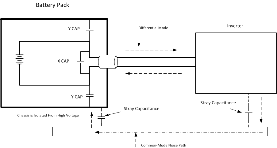
GUID-298BDFE2-1326-49E1-82ED-AA0AC944BCF6-low.gifFigure 3-2 X-Y Caps

Design Considerations

  • Device placement is important. The daisy-chain cable should not be resting on the busbar or metal enclosure surface.