SLUAAF8 October 2021 BQ24707 , BQ24707A , BQ24725A , BQ24735 , BQ24770 , BQ24780S , BQ24800 , BQ25700A , BQ25708 , BQ25710 , BQ25720 , BQ25730 , BQ28Z610-R1 , BQ4050 , BQ40Z50 , BQ40Z50-R1 , BQ40Z50-R2 , BQ40Z80
2.1.1 I2C System Differences
The setup process is slightly more involved for I2C broadcast mode. The charger device address, charge current register, charge voltage register, and broadcast pacing need to be programmed to the flash memory of the gauge.
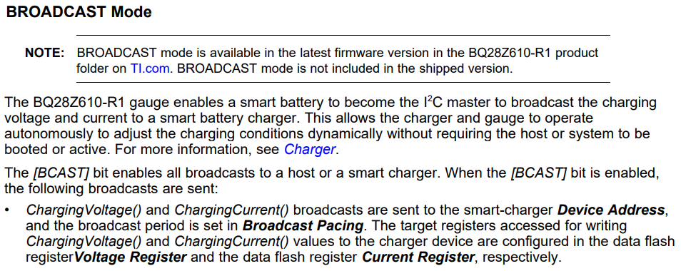
The BQ28Z610-R1 is currently a unique case, it can broadcast ChargingCurrent() and ChargingVoltage() in a 2-byte format to chargers that meet its broadcast mode transmission formatting and use I2C for communication. More information is found in the gauge TRM:
For the correct formatting, the charger must have a 2-byte charge current and charge voltage register, and it must not have any other bits in the same register used to configure the charger. The gauge will write the whole 2-byte register, so any configuration information would be overwritten. If the bits are reserved for a TI charger, like the BQ25730(8), it does not matter what the gauge writes to the register, the reserved values are not modified. Refer to Section A for more specific information about the gauge setup for I2C.