SLUAAO7 March 2023 BQ24640 , BQ25173 , BQ25713 , BQ25798
- Abstract
- Trademarks
- 1Introduction
-
2Supercapacitors Charging Key
Care-Abouts and Implementations
- 2.1 Supercap Charge Profile
- 2.2 Linear Based Supercap Charger
- 2.3 Switch-Mode Buck Converter Based Supercap Charger
- 2.4 Modifying Li-ion Chargers to Charge Supercaps
- 2.5 Using a Li-ion Buck-Boost Integrate FET Charger to Charge a Supercap or Li-ion Battery
- 2.6 Using a Buck-Boost Controller with External FETs to Charge a Supercap
- 3Summary
- 4References
2.5 Using a Li-ion Buck-Boost Integrate FET Charger to Charge a Supercap or Li-ion Battery
Modifying an integrated FET, host controlled buck-buck boost charger to charge a supercap is best if
- There is a need to switch between Li-ion battery and supercap charging with a single charger IC (using host software to change the charge settings).
- The input voltage to the charger can be higher or lower than VREG.
- 1.0 A < ICHG < 5.0 A
- The supercap’s capacitance is medium to high or fast charging time is required
The BQ25798 + TPS25221 reference design block diagram is shown below. In this configuration, the charger can be used in a cradle to charge either a supercap or a LiIon battery pack. A mechanical switch is likely required to inform the host, and therefore the charger, which storage element is being charged and how to reset the charger's registers.
 Figure 2-7 BQ25798 Plus TPS25221 Supercap and Li-ion charging Reference Design Block Diagram
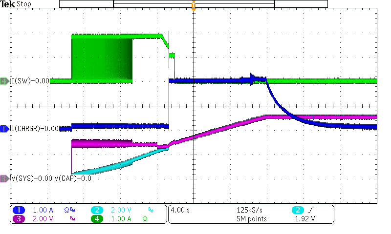
A complete charge cycle using the BQ25798 and TPS25221 to charge a 10F supercapacitor to 5 V with ICHG=2 A and VBUS = 5 V is shown in Figure 2-8.
 Figure 2-8 BQ25798 Plus TPS25221 Charge Cycle of a 10 F Supercap with ICHG=2 A
The pink trace is V(SYS) and blue trace is V(CAP). While V(CAP) < 2.5 V, the charger provides 100 mA trickle charge and the switch provides 1.9 A, after exiting the thermal fault duty cycle phase. Then the host turns off the switch and the charger provides the entire 2 A fast charge current. It is possible to parallel multiple switches to share the losses, reduce their time in thermal fault and allow for higher charge current. In this example, the host disabled charge termination so the STAT pin (not shown) never changes state and the converter operates in CV mode indefinitely to keep the supercap at 5 V.