SLUAAO7 March 2023 BQ24640 , BQ25173 , BQ25713 , BQ25798
- Abstract
- Trademarks
- 1Introduction
-
2Supercapacitors Charging Key
Care-Abouts and Implementations
- 2.1 Supercap Charge Profile
- 2.2 Linear Based Supercap Charger
- 2.3 Switch-Mode Buck Converter Based Supercap Charger
- 2.4 Modifying Li-ion Chargers to Charge Supercaps
- 2.5 Using a Li-ion Buck-Boost Integrate FET Charger to Charge a Supercap or Li-ion Battery
- 2.6 Using a Buck-Boost Controller with External FETs to Charge a Supercap
- 3Summary
- 4References
2.2 Linear Based Supercap Charger
A step-down only linear regulator-based charger is best for applications where
- The input voltage is higher than VREG.
- ICHG is low, typically < 1.0A
- The supercap's capacitance is low or charging time is not critical
- The system load can be connected directly to the supercap
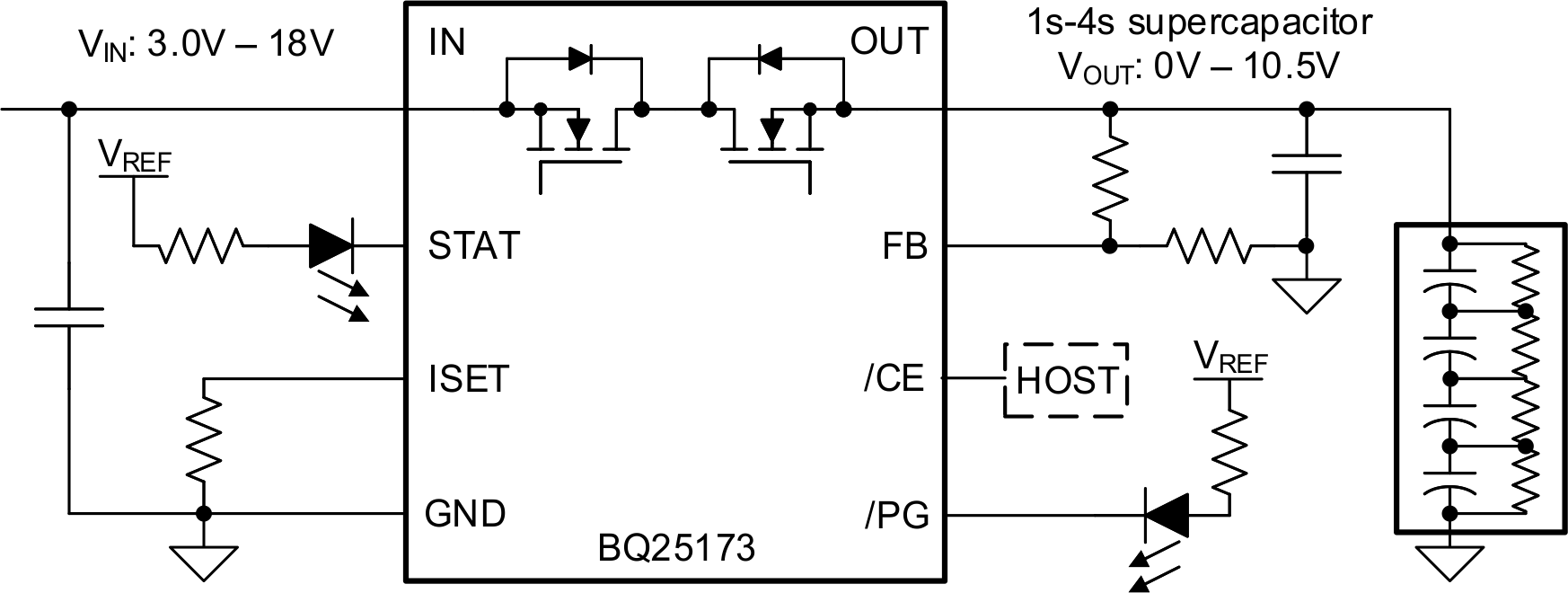
The BQ25173 is a linear regulator based supercap charger. The FB pin resistors set the CV voltage, VREG, and the ISET resistor sets the CC current, ICHG.
 Figure 2-2 BQ25173 Supercap Charger Block
Diagram
Figure 2-2 BQ25173 Supercap Charger Block
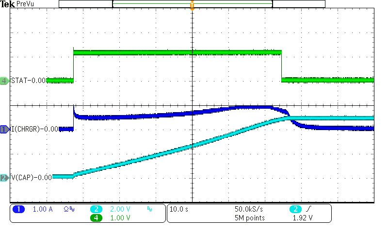
DiagramA complete charge cycle of the BQ25173 charging a 10F supercap to 5 V with ICHG=800mA and V(IN)=5.5 V is shown in Figure 2-3.
 Figure 2-3 BQ25173 Charge Cycle of a 10 F
Supercap to 5.5 V with 800 mA Charge Current
Figure 2-3 BQ25173 Charge Cycle of a 10 F
Supercap to 5.5 V with 800 mA Charge CurrentNote the thermally reduced charge current at the beginning of the cycle. The STAT pin goes low when the supercap voltage reaches 98% of the regulation voltage. The charger stays in CV to maintain the supercap voltage at 5 V.