SLUUBA2B March 2015 – November 2015
2.2 Equipment Setup
- Set PS#1 for 5-V DC, 1-A current limit and then turn off the supply.
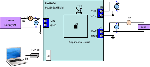
- Connect the output of PS#1 in series with a current meter (multimeter) to J1 (VBUS and GND).
- Connect a voltage meter across TP3 (VBUS) and TP6 (PGND).
- Turn on the Load, set to constant voltage mode and output to 2.5 V. Turn off (disable) Load. Connect Load in series with a current meter (multimeter), ground side, to J4 (BAT+ and GND) as shown in Figure 3.
- Connect a voltage meter across J4 (BAT+ and GND).
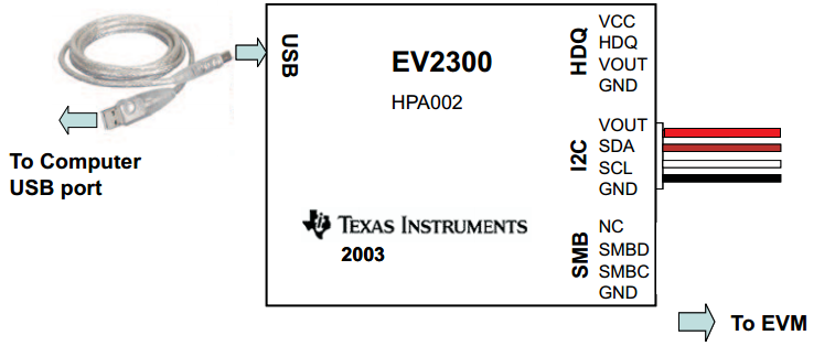
- Connect the EV2300 USB interface board to the computer with a USB cable and from I2C port to J8 with the 4-pin cable. The connections are shown in Figure 2.
- Remove jumper (if installed) from JP5.
- Install shunts as shown in Table 3.
- Turn on the computer. Launch the bq2589x evaluation software, choose Charger as shown in Figure 4, then choose the appropriate .bqz file as shown in Figure 5.
- Select the Charger_1_00-bq25890-895.bqz file, if evaluating the bq25890 or bq25895
- Select Charger_1_00-bq25892-896.bqz, if evaluating the bq25892
- If an error pops up stating the communications adapter was not found (Figure 6), click OK to proceed. Next, unplug and re-plug the adapter.
- Choose Field View, as shown in Figure 9. The main window of the bq2589x software is shown in Figure 10.
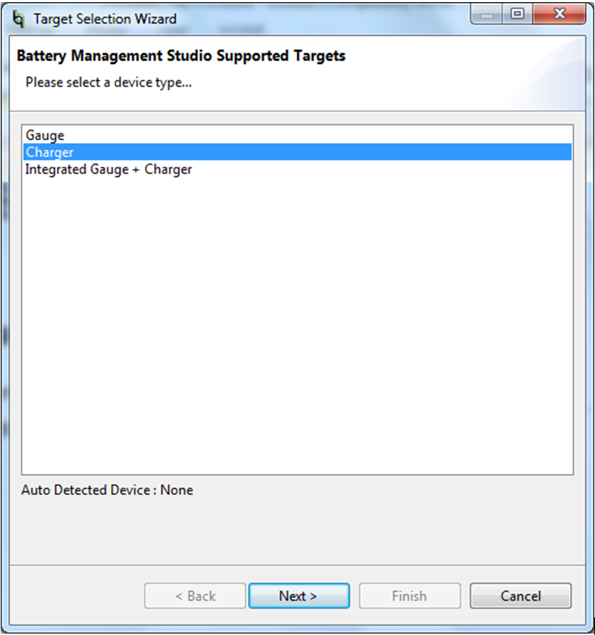 Figure 4. Start Window of the bq2589x Evaluation Software
 Figure 5 illustrates the following part selection options:
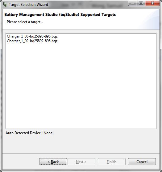 Figure 5. Part Select Window of the bq2589x Evaluation Software
  Figure 6. Communications Adapter Error
 If an error pops up stating there is no acknowledge from the device (Figure 7), click OK to proceed and then pick the appropirate I2C address from the drop-down menu in the GUI (see the Procedure section).
 Figure 7. Acknowledge Error
 Check the connection status of the EV2300 in bqStudio by going to View → DashBoard. A panel on the left-hand side should appear, with the status of the EV2300 at the top (Figure 8).
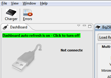 Figure 8. DashBoard Status Tab
 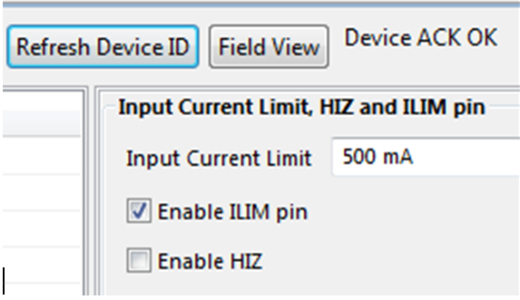 Figure 9. Select Field View
 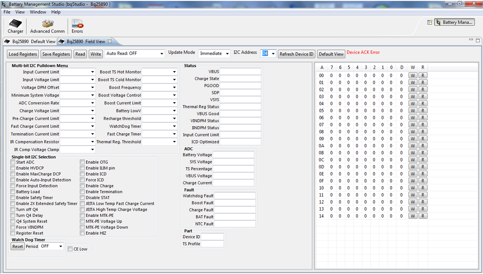 Figure 10. Main Window of the bq2589x Evaluation Software