SLUUBG8C November   2018  – October 2021


  1.   Trademarks
  2. 1 Introduction
  3. 2 Description
  4. 3 Features
    1. 3.1 I/O Description
    2. 3.2 Jumpers (Shunt) Setting
  5. 4 Electrical Specifications
  6. 5 Test Summary
    1. 5.1 Definitions
    2. 5.2 Equipment
      1. 5.2.1 Power Supplies
      2. 5.2.2 Function Generators
    3. 5.3 Equipment Setup
      1. 5.3.1 DC Power Supply Settings
      2. 5.3.2 Digital Multi-Meter Settings
      3. 5.3.3 Two-Channel Function Generator Settings
      4. 5.3.4 Oscilloscope Setting
      5. 5.3.5 Jumper (Shunt) Settings
      6. 5.3.6 Bench Setup Diagram
  7. 6 Power-Up and Power-Down Procedure
    1. 6.1 Power Up
    2. 6.2 Power Down
  8. 7 Test Waveforms (CL=0pF) With Different DT Configurations
    1. 7.1 DT Connected to VCCI (J-DT Option B in Table 1-1 )
    2. 7.2 DT Pin Floating or Left Open (J-DT Option A in Table 1-1 )
    3. 7.3 DT Pin Connected to RDT (J-DT Option C in Table 1-1 )
  9. 8 Schematic
  10. 9 Layout Diagrams
  11. 10List of Materials
  12. 11Revision History

DT Connected to VCCI (J-DT Option B in Table 3-2)

The dead time (DT) between the outputs of the two channels is decided by inputs (see Figure 7-1). Overlap between two output channels is allowed. Figure 7-1 shows a waveform with overlapped operations.
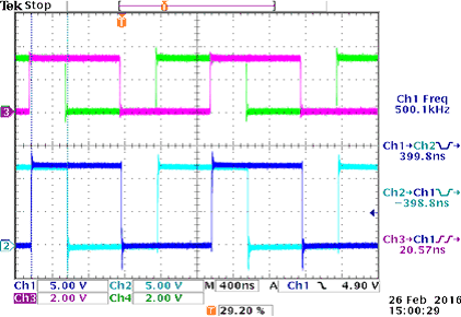
GUID-BB4AA91D-9166-45B4-9A0F-AE25EDF39124-low.gifFigure 7-1 Overlap is Allowed When DT Connected to VCCI (Channels 3 and 4 are PWM Inputs, Channels 1 and 2 are Driver Outputs)