SLVA488B January 2014 – January 2021 DRV8434 , DRV8811 , DRV8818 , DRV8821 , DRV8824 , DRV8825
2.6 Position Control: Number Of Steps
The closed loop capabilities of a stepper are not limited to accurately controlling the speed. Since in essence the controller is counting the very same steps which are being generated, knowledge of step position is continuously being updated. Every time a step is executed, the variable StepPosition is updated according to step rotation direction. For example, if the motor is rotating clockwise (DIR = HI), the StepPosition variable is incremented, whereas if the motor is rotating counterclockwise (DIR = LO), then the StepPosition variable is decremented.
The notions of motor rotation as clockwise or counterclockwise are directly dependent to how the motor was wired and the motor itself.
The variable StepPosition can be read in real time to obtain information as to where the motor is at any given point in time.
On this application note, however, the controller is always operating in Position Control mode. The variable NumberOfSteps is programmed to hold the entire number of steps which will be executed. Since this is a 32-bit variable, the total number of steps could be a significantly large number, in which case the motor would in essence be operating in free running mode. However, if the NumberOfSteps count is small, then the motor will stop once the total NumbeOfSteps have been executed.
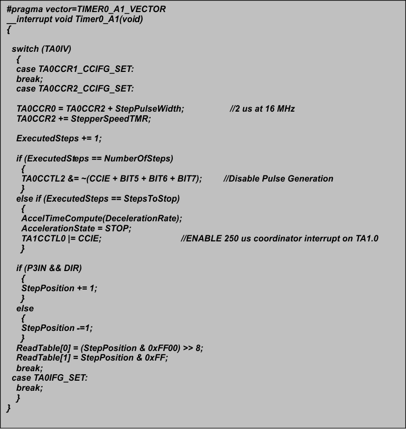
The previous mechanism is achieved by counting how many steps have been executed and comparing this number to the NumberOfSteps command. This is taken care of on the Timer A0.2 ISR as shown in Figure 2-10.
Notice this ISR is in charge of a few tasks we have described earlier and which are of crucial importance to generating accurate stepping information. These tasks are:
- Generation of the STEP pulse by configuring when the STEP clear takes place. Timer A0.0 is in charge of returning the STEP signal to LO.
- Configuring the TIMERA0.2 to generate the next step according to the current step rate, or StepperSpeedTMR, which is the timer equivalent of the current rate in Hz.
- Determining whether the current generated step is the last step to execute. This happens when ExecutedSteps is equal to NumberOfSteps.
- If the current generated step is equal to StepsToStop value, then the engine is commanded to start a deceleration profile.
- Update StepPosition according to motor direction.
 Figure 2-10 Timer A0.2 ISR