SLVA488B January 2014 – January 2021 DRV8434 , DRV8811 , DRV8818 , DRV8821 , DRV8824 , DRV8825
1 Introduction and Problem Statement
Driving a stepper motor can be a daunting task. Whereas, providing a voltage at the terminals of a DC motor causes immediate rotation, on a stepper motor, careful magnetic field commutation must be applied in order to obtain the same behavior. In the not so distant past, said electromagnetic commutation was achieved by coding powerful microprocessors to coordinate the phase and current information administered into the power stage.
With the advent of high integration on monolithic integrated circuits, it became simpler to take into hardware all the blocks once generated through code. A stand alone IC could now control even the most intricate subjects such as phase commutation and microstepping without the need of precious microcontroller resources.
 Figure 1-1 Stepper
Control Logic and Power Stage
Figure 1-1 Stepper
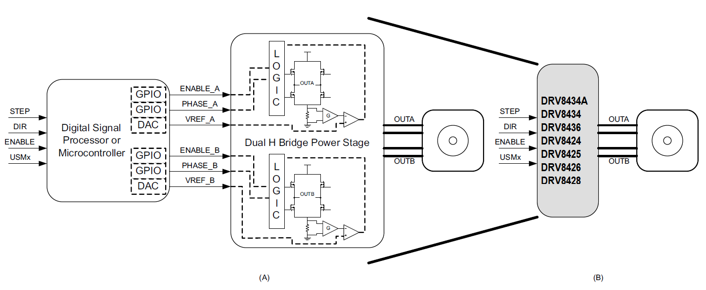
Control Logic and Power StageFigure 1-1 shows the level of integration which can be obtained when the code inside of a microcontroller, and in charge of causing stepper commutation, is concatenated along with the power stage into a single chip solution. Notice that in both scenarios a series of simple control signals exist. A STEP pulse is used to generate steps or microsteps; a DIR signal defines the direction of rotation; the ENABLE line determines whether the power stage is enabled or not; and the User Mode bits are used to select a degree of microstepping.
Controlling a stepper, however, can still benefit from the usage of a microcontroller. Tasks such as speed and position control, acceleration and deceleration, homing, etc. still require accuracy and precision which a microcontroller can easily supply. The question we must ask is: Will the application processing unit be asked to compute all the parameters related to stepper motion, or will a smaller and more cost economical microcontroller be used to tackle the tasks at hand?
Using a smaller microcontroller with each driver to perform the aforementioned tasks is advantageous if numerous steppers are to be controlled. In this fashion, the application processor can utilize its real time resources to properly coordinate application intensive aspects, while the small microcontrollers deal with the intricacies of controlling the stepper motors.
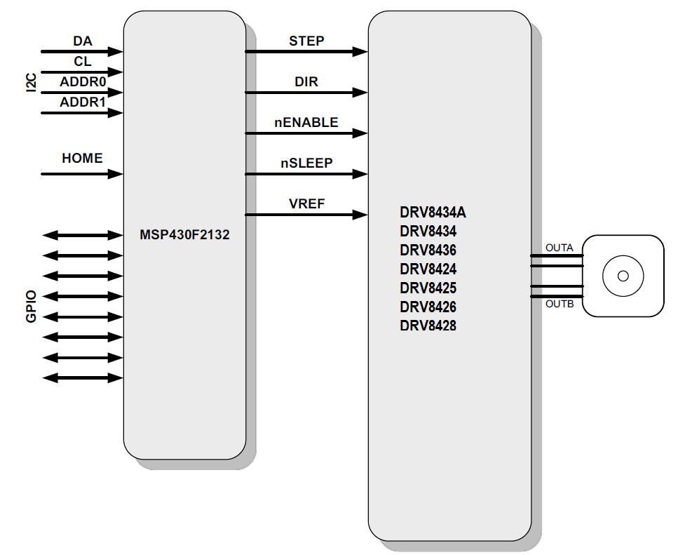
This application note details an implementation using an MSP430F2132 microcontroller and a DRV8434/24 device which has an internal indexer bipolar stepper microstepping power stage. Combined, they form a module capable of receiving commands from a controller through an I2C bus, and which will then undertake all the actions to control the stepper motor both in speed and position. In order to best utilize the available resources, a series of GPIO terminals were added, which will provide extra functionality to the main processor. Figure 1-2 shows a block diagram of the proposed implementation.
While the implementation considers GPIO controlled stepper drivers, it can be adapted to SPI controlled drivers. Some of the newer TI stepper drivers have integrated stall detection which can eliminate the need for external homing and end of travel sensors as well as safeguard the electrical and mechanical systems from wear and tear. Stepper drivers such as the DRV8434S offer stall detection using SPI control and digital implementation whereas the DRV8434A offer stall detection using GPIO control and analog implementation. In addition newer TI stepper drivers offer integrated current sensing eliminating the need for external current sense resistors, not only reducing cost and PCB space but also cutting power loss and heat. Furthermore, integrated smart tune technology in the newer devices increases efficiency and minimize audible noise from the stepper motor.
 Figure 1-2 Intelligent Stepper Controller Block Diagram