SLVA980B April 2018 – April 2021 DRV8304 , DRV8306 , DRV8320 , DRV8320R , DRV8323 , DRV8323R , DRV8350 , DRV8350R , DRV8353 , DRV8353R , MCT8316Z
1 Application Brief
Introduction
Brushless-DC (BLDC) motors remain an important and fast-growing motor type with many performance benefits over brushed-DC (BDC) and stepper motors. BLDC motors are more efficient, higher power, higher torque, quieter, longer lifetime, and higher speed compared to their BDC counterparts. Today, we see many different products that specifically advertise themselves as having “brushless” technology. Being able to keep up with the market trends is important in order to design a product that is relevant and successful on the market. Some examples of these products are cordless power and garden tools, cordless vacuums, drones & remote-control toys, fans and air purifiers, and automated window blinds.
However, the difficulty of implementing a BLDC motor in a customer system remains a large barrier to entry for many product design teams, especially when comparing the complexity of BLDC control versus a BDC motor. This even applies to systems using censored trapezoidal control which will be the main topic of this document.
Brushed-DC Systems
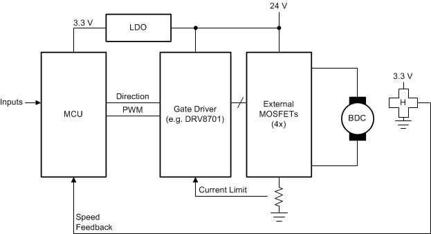
If we look at a typical medium-power brushed-DC motor system, we have four external MOSFETs and an associated H-bridge gate driver (for example, DRV8701). A low-dropout regulator (LDO) generates 3.3V from the main motor supply for the microcontroller (MCU) and Hall-effect sensor (the LDO may be integrated into the gate driver). The system MCU takes inputs (buttons, commands, and so on) and controls the motor using two output, a direction signal (clockwise or counterclockwise spinning) and a PWM signal (0% to 100% duty cycle at a fixed frequency). The Hall-effect sensor is used for motor speed feedback to the MCU.
 Figure 1-1 Brushed-DC motor system
The control loop used in such a system can be either a speed control loop or a position/servo control loop. The Hall-effect sensor output frequency is directly proportional to the motor speed and is used to close the speed control loop. If we apply an integrator/accumulator to the Hall-effect sensor signal, we can determine the motor position and perform a position control loop.
 Figure 1-2 Brushed-DC motor speed control loop
Traditional Brushless-DC Systems
Looking at a similar BLDC system, we can understand why engineers would be concerned about the complexity of implementing a brushless-DC motor in the same way. The traditional solution for BLDC control involves three ½ H-bridge gate drivers and six external MOSFETs. These gate drivers feature a 6x PWM interface, such that each FET requires a controlling signal (six input signals in total). The brushless-DC motor requires electrical commutation, meaning that it is the system’s responsibility to keep the motor spinning by energizing the phases in the correct sequence. For a sensored control scheme, three Hall-effect sensors are integrated in the motor to give position feedback. In some motors, the Hall-effect sensors are replaced by Hall elements, which have analog outputs and require additional comparators to implement proper feedback. As seen in Figure 1-3, the MCU requirements increase dramatically in terms of inputs and output required compared to a brushed-DC motor scheme.
 Figure 1-3 Traditional brushless-DC motor system
Simplified Brushless-DC Systems
To “simplify” the brushless-DC system, let’s examine DRV8306, a three-phase Smart Gate Driver. This device integrates a six-step (trapezoidal) commutation table in order for the DRV8306 to control the brushless-DC motor commutation. This offloads processing requirements from the MCU, as well as reduces the number of GPIOs required on the MCU. The integration of the commutation table allows the DRV8306 device to implement a BLDC design as simple as a brushed-DC motor system: a direction and PWM command. The DRV8306 also integrates Hall element comparators, which allow it to be used with either Hall-effect sensors or Hall elements without additional comparators or circuits. All three Hall signals are combined in the DRV8306 to send one speed feedback signal to the MCU.
 Figure 1-4 Simplified brushless-DC motor system
We see in Figure 1-5 that the control loop is similar to that of a brushed-DC motor once the motor commutation is handled by the gate driver.
This allows for a system with reduced complexity and simple control. The motor control requirements from the MCU are identical between the brushed-DC Motor system example given earlier and this simplified brushless-DC motor example.
 Figure 1-5 Simplified brushless-DC motor speed control loop
Conclusion
Design complexity is cited as a common reason for not implementing brushless-DC motors in products, and while this is true for the traditional brushless-DC system, devices like DRV8306 allow brushless-DC motor control to be simplified so that the control complexity is similar to a brushed-DC system.
Device Recommendation
The DRV8306 is not the only device that can execute trapezoidal control of a sensored motor, other devices may be selected based on the necessary system requirement. The MCT8316Z is another similar device which also integrates the power stage MOSFETs and current sensing resistors for motor up to 8-A peak. The DRV8306 and MCT8316Z can support Hall element inputs while other devices listed below only support Hall-effect sensors without external comparators (in 1x PWM mode).