SLVAF16A March 2021 – December 2021 AFE7920 , AFE7950 , TPS541620 , TPS62912 , TPS62913
2.1 Test Methodology
Signal-to-Noise Ratio (SNR, dBFS)
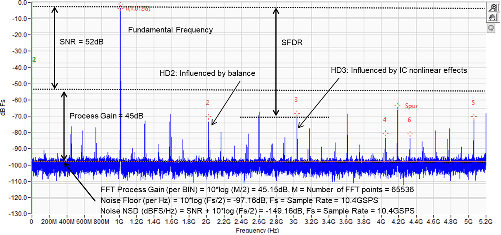
The SNR is the ratio of the rms signal amplitude to the rms value of the sum of all spectral components excluding DC, HD2 to HD9, fS / 2, fS / 2 – fIN. The difference between SNR (dBc) and SNR (dbFS) is the difference between the fundamental amplitude and full scale.
Phase Noise (dBc/Hz)
The phase noise parameter measures the frequency noise or jitter that is related to the sampling clock. Phase noise measurement sweeps from a very low frequency offset (~100 Hz) out to over 10 MHz releative to the carrier frequency. This measurement examines low frequency spurious and and noise that may come from the clock or the power supply at the transmitter output.
Harmonic Distortion (dBc or dBFS)
A harmonic is a spectral component that is an integer multiple of the driven analog input frequency. For example, the frequency of the second harmonic is twice the analog input. Most ADCs have specifications for one or more harmonics. Typically, the second and third harmonics are singled out because they account for the worst performance of all the harmonics. Harmonic distortion, no matter the order, is the ratio of the rms signal amplitude to the rms value of the specified harmonic component, reported in dBc or dBFS. ADCs are nonlinear devices, therefore output FFT captured will be rich in spectral components.
Spurious-Free Dynamic Range (SFDR, dBc or dBFS)
The SFDR is the ratio of the rms value of the signal to the rms value of the peak spurious spectral component for the analog input frequency that produces the worst result. In most cases, SFDR is either the second or third harmonic (HD2 or HD3) of the input signal applied to the ADC. SFDR is intended to capture the spurious performance and not be inadvertently misled by spectral content close in to the carrier due to the phase noise spread. As such, in many of the FFT plots a handful of bins around the fundamental are notched so that the true highest spur is captured.
Noise Spectral Density (NSD, dBFS/Hz)
The NSD is defined the entire noise power, per unit of bandwidth, sampled at an ADC’s input. NSD is effectively the ADCs’ SNR plus the power of the noise spread across the entire Nyquist band, which is equal to half the sample frequency, or Fs/2. Therefore, NSD = SNR + 10*log(Fs/2).
For a visual description of how to read SNR, SFDR, Harmonic Distortion, and NSD, refer to Figure 2-1.
 Figure 2-1 FFT showing SNR, SFDR, NSD,
and Harmonic Distortion