SLVAF35 February 2021 DRV8714-Q1 , TPS2HB16-Q1
5.2 Adjustable Supply Voltage Approach
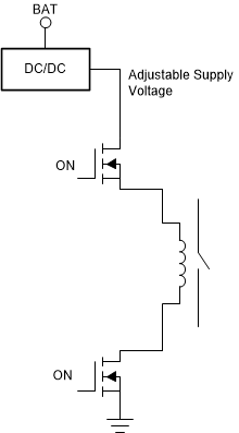
In above description, battery voltage is supplied to drive the contactor coil. However, the battery voltage is not a fixed value and has a large range during normal operation. That is why dedicated PWM control is introduced to obtain desired current. Because the current is determined by the applied supply voltage divided by the coil resistance, an adjustable supply voltage to the coil is another option. Figure 5-3 shows the adjustable supply voltage applied to drive the contactor coil. A DC/DC converter is the best solution converting battery voltage to adjustable supply voltage. And high-side switch can be eliminated if DC/DC converter integrates Enable/Disable control.
 Figure 5-3 Current Generation with Adjustable supply voltage.
 It is more like moving PWM control from the coil driving switches to the DC/DC converter. The DC/DC output voltage depends on the coil resistance for a required current. Thus, the output voltages during pickup phase and hold phase are not same. Meanwhile, it is better to integrate current sense to check whether the current flowing through the coil equals to the required value.