SLVAF35 February 2021 DRV8714-Q1 , TPS2HB16-Q1
5 Coil Driving Implementation
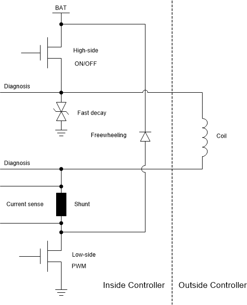
It is more preferable from the system perspective to use both high-side and low-side switches to drive the contactor coil for safety reasons. The coil will always be energized and cannot be shut off when short-circuit failure happens if only the high- or low-side switch is used. The failure is in line with a short circuit to the battery on the high-side switch and short circuit to ground on the low-side switch. A large current flows through the coil and cannot be switched off, thus the coil might be damaged due to high power dissipation.
 Figure 5-1 Implementation Example of Coil
Driving Circuit
Figure 5-1 Implementation Example of Coil
Driving CircuitFigure 5-1 shows how to drive contactor coils with both high- and low-side switches. It is supplied by the battery voltage. Both high- and low-side switches can do PWM control, but it is more suitable to use a low-side switch for high-frequency PWM control up to 25 kHz. Here the high-side switch acts as ON/OFF control and protects the coil while short-circuit failures happen at the low-side terminal. A freewheeling diode is necessary, because the current through the coil must not interrupt suddenly while turning off the low-side switch. Otherwise, there could be a very large voltage spike due to the coil inductance and probably damage the components. A fast-decay diode is added to generate a large reverse voltage across the coil when both high- and low-side switches are turned off. This large reverse voltage makes the coil current drop to zero quickly. Meanwhile, diagnosis features at both high- and low-side terminals are necessary for automotive applications.