SLVUBX8B October 2020 – December 2021 TPS2661
- Trademarks
- 1Introduction
- 2Description
- 3Schematic
- 4General Configurations
-
5Test Setup and Procedures
- 5.1 Overload Protection Test
- 5.2 Output Short-Circuit Test
- 5.3 Input Undervoltage Protection Test
- 5.4 Output Undervoltage Protection Test
- 5.5 Output Overvoltage Protection Test
- 5.6 TPS26612 Overload Protection Test
- 5.7 Current Limiting for VIN < –Vs
- 5.8 Surge Protection Test (Current Input, CH1)
- 5.9 Surge Protection Test (Analog Output, CH2)
- 6EVAL Board Assembly Drawings and Layout Guidelines
- 7Bill Of Materials (BoM)
- 8Revision History
5 Test Setup and Procedures
In this user's guide, the test procedure is described for the TPS26610 and TPS26612 devices.
Make sure the evaluation board has default jumper settings as shown in Table 5-1.
Table 5-1 Default Jumper Setting for
TPS2661EVM eFuse Evaluation Board
| J4 | J5 | J6 | J7 | J10 | J11 | J12 | J14 |
J15 |
J16 |
J17 |
J18 |
J19 |
J20 |
|---|---|---|---|---|---|---|---|---|---|---|---|---|---|
| 1–2 | Open |
1-2 |
Open | 2-3 |
Open |
Open |
2-3 |
2-3 |
Open |
Install |
Open |
Install |
Open |
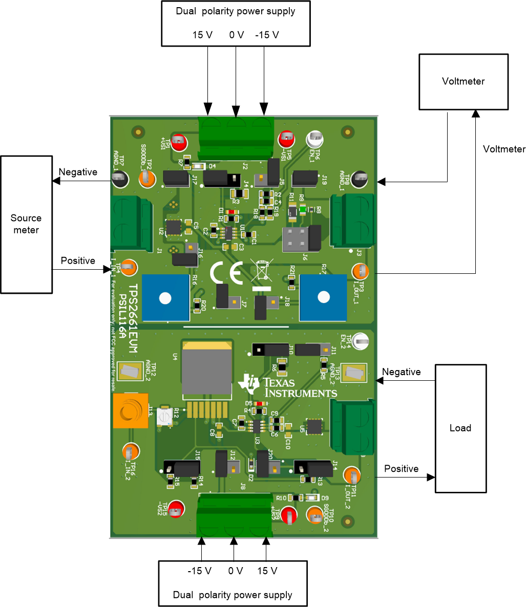
 Figure 5-1 TPS2661EVM Setup With Test
Equipment