SLVUC73B January   2022  – February 2024 TPS7H4003-SEP


  1.   1
  2.   TPS7H4003EVM Evaluation Module (EVM)
  3.   Trademarks
  4. 1TPS7H4003EVM Overview
    1. 1.1 Features
    2. 1.2 Applications
  5. 2TPS7H4003EVM Default Configuration
  6. 3TPS7H4003EVM Initial Setup
  7. 4TPS7H4003EVM Testing
    1. 4.1 Output Voltage Regulation
    2. 4.2 Output Voltage Ripple
    3. 4.3 Soft Startup
    4. 4.4 Transient Response to Positive and Negative Load Step (9A to 18A to 9A)
    5. 4.5 Loop Frequency Response
    6. 4.6 Setup
  8. 5TPS7H4003EVM Schematic
  9. 6TPS7H4003EVM Bill of Materials (BOM)
  10. 7Board Layout
  11. 8Support Resources
  12. 9Revision History

Output Voltage Regulation

  1. Turn-on input DC source (5V).
  2. Turn on the e-load and sweep load current from 0A to 18A. The monitored output voltage at TP12 (VOUT) is at or near 1V across the entire current load sweep as shown in Figure 4-1.
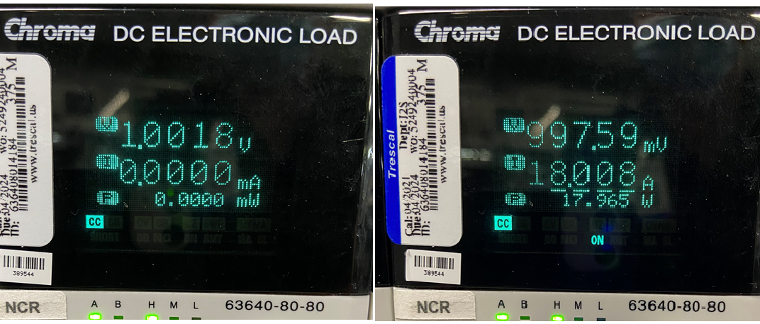
GUID-20220114-SS0I-QMKS-PBNG-VDKCBC73ZQK4-low.png Figure 4-1 Output Voltage Regulation