SLYY109B February 2021 – March 2022 HD3SS3212 , HD3SS460 , TPD4S311A , TPD6S300A , TPD8S300 , TPS25740A , TPS25750 , TPS65982 , TPS65983B , TPS65987D , TPS65988 , TPS65994AD , TUSB1042I , TUSB1046A-DCI , TUSB1210 , TUSB1310A , TUSB320 , TUSB542 , TUSB544 , TUSB546A-DCI , TUSB564
- At a glance
- Authors
- 3
- Introduction
- Data and power roles
- USB Type-C UFP sink: USB 2.0 without USB PD
- USB Type-C DFP: USB 2.0 without USB PD
- USB Type-C DRP/DRD USB 2.0 without USB PD
- USB Type-C DRP/DRD: USB 2.0 with USB PD
- USB 3.1 Gen 1 (SuperSpeed) and Gen 2 (SuperSpeed+)
- Alternate Mode
- USB Type-C pinout and reversibility
- Conclusion
- References
USB Type-C UFP sink: USB 2.0 without USB PD
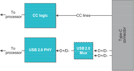
The most simple and likely most common application is a UFP USB 2.0 without USB PD (≤15 W). Common applications include anything USB-powered today that does not require SuperSpeed data, such as a mouse, keyboard, wearables or various other small electronics. Figure 2 highlights the necessary functional blocks for a USB Type-C UFP USB 2.0 system.
 Figure 2 Type-C UFP USB
2.0 without PD block diagram.
Figure 2 Type-C UFP USB
2.0 without PD block diagram.At this point, we will assume that you understand the USB Type-C connector pinout and how reversibility works; if not, see Figure 13. Note that the USB 2.0 physical layer (PHY) is no different than previous USB 2.0 designs with a Type-A or Type-B connector. It serves as the physical layer between the data from USB’s D+ and D– lines to the USB 2.0 Transceiver Macrocell Interface (UTMI) plus low-pin interface (ULPI) for the application processor to manage.
USB 2.0 PHYs are often integrated into processors or microcontrollers; however, there are discrete PHYs available to integrate USB functionality into your design. The configuration channel (CC) logic block introduced in the USB Type-C specification determines cable detection, cable orientation and current-carrying capability.
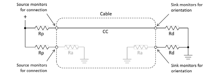
- Cable detection occurs when one of the two CC lines pulls down (see Figure 3). A DFP will have both of its CC pins pull up with resistor Rp, and a UFP will have both of its CC pins pull down with resistor Rd [1]. Once a DFP processor detects that one of its CC lines is pulled down, the DFP will know that a connection has been made.
- Cable orientation is based on which CC line pulls down (if CC1 pulls down, the cable is not flipped; but if CC2 pulls down, the cable is flipped). For nonactive cables, the remaining CC line remains open; for active cables, the remaining CC line will pull down with Ra.
- The values of Rp determine the current-carrying capability. USB Type-C can natively support either 1.5 A or 3 A. A DFP can advertise its current-carrying capability with a specific value pullup resistor. A UFP has a fixed- value pulldown resistor (Rd) such that when connected, it forms a voltage divider with Rp. By sensing the voltage at the center tap of the voltage divider, a UFP can detect the DFP’s advertised current.
 Figure 3 CC logic
pullup and pulldown termination. (Source: USB Type-C
specification v1.2, Figures 4 and 5 pullup/pulldown CC
model)
Figure 3 CC logic
pullup and pulldown termination. (Source: USB Type-C
specification v1.2, Figures 4 and 5 pullup/pulldown CC
model)The last block is a USB 2.0 multiplexer (often called a high- speed mux). The dotted outline in Figure 2 represents an optional block not required by the USB Type-C specification. To understand the purpose of the mux, it’s important to understand how flipping the cable affects data flow. In a USB Type-C receptacle, there are two pairs of D+/D– lines for a single channel of USB 2.0 data. In one orientation, data flows down one of the pairs. In the flipped orientation, data flows down the other pair. The USB Type-C specification allows shorting the pairs together, D+ to D+ and D– to D–, to create a stub. Although it’s not required, some designers elect to include a USB 2.0 mux in their system to improve signal integrity.
Texas Instruments (TI) offers a variety of devices for UFP applications with USB 2.0 data and no USB PD. These devices from TI offer a compact solution for CC logic that can determine cable detection, orientation and current- carrying capability.