SLYY226 January 2024 BQ79731-Q1 , DRV3901-Q1 , DRV3946-Q1 , TPSI2140-Q1 , TPSI3050-Q1
- 1
- Overview
- At a glance
- Evolving the powertrain to domain and zone control
- Technologies enabling intelligence within BMS: the MCU
- Technologies enabling intelligence within the BMS: wireless capability
- Technologies enabling intelligence within the BMS: the intelligent junction box
- Digital twin, machine learning and fleet management
- Conclusion
- Additional resources
Evolving the powertrain to domain and zone control
Historically, designers added MCUs to vehicle designs where sensors or actuators required more intelligence, creating a need for more complex control or communication. But combining the additional complexity of options within different vehicle platforms resulted in complex vehicle system descriptions, high development effort and challenging maintenance. For example, over-the-air updates required testing against all configurations, adding significant time and complexity to the process.
To help solve the challenges of complexity, weight and cost, domain and zone control architectural concepts have emerged. Take a look at what these different architectures require of the subsystems within a vehicle.
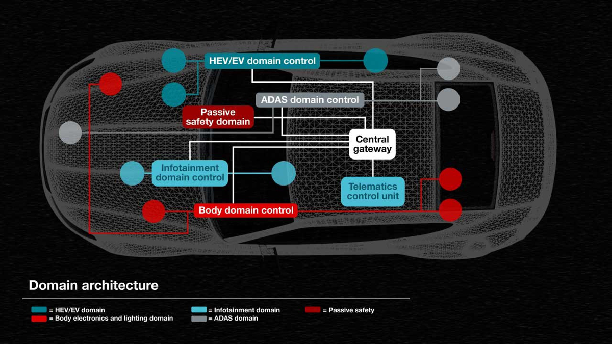
In a domain architecture, each domain accumulates certain electronic control units (ECUs) based on related function. As an example, the onboard charger, DC/DC converters, traction inverter and BMS would encompass the HEV/EV control domain and share a single, centralized MCU, as shown in Figure 1. This reduces the number of distributed MCUs, puts functions in proximity to simplify interfacing, and enables the sharing of computing resources by centralizing identical functions into a single MCU. For example, the OBC and inverter would not be operating the same time and would instead share computing capacity.
 Figure 1 The domain control architecture.
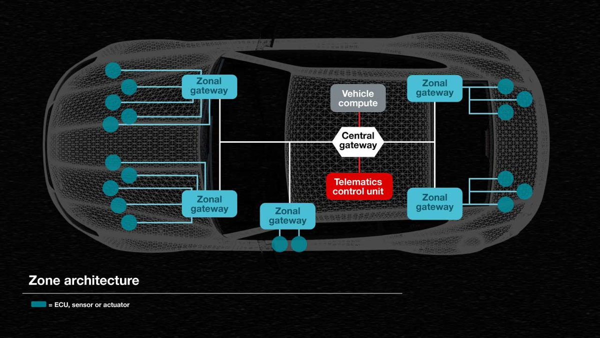
Zone architecture takes the idea of domain control one step further, with functions grouped into zones and controlled by MCUs based on the location in the vehicle, as shown in Figure 1. The zones are connected through a high-bandwidth communication backbone, since distributed sensors and actuators among zones require timely communication. While reducing the number of required MCUs, zone architecture reduces wiring harness complexity and weight, resulting in further cost savings and increased driving ranges. Hardware and software update cycles are decoupled and automakers can move to a service-based software structure.
 Figure 2 The zone control architecture.
While domain and zone architectures have different advantages and challenges, they can also coexist in the same vehicle within a crossover architecture. For example, the BMS can use a domain control approach while automated driver assistance systems (ADAS) leverages zone at the same time. The transformation of powertrain to domain or zone control architectures often happens later, after addressing application-specific challenges in the areas of functional safety and system agility. Following the original philosophy to centralize MCU functions as much as possible means that the BMS must communicate through sophisticated or standardized interfaces with no MCU intelligence at the edge. This type of implementation meets the goal to reduce the number of MCUs.
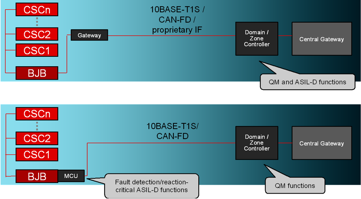
However, a technical challenge then arises: cell or pack high-voltage chipset data (voltage, current and temperature readings and related safety measures) will transfer as raw data. Since fault detection time interval, fault reaction time interval and safe states are tightly defined, the available bandwidth of the interface needs close observation and optimization and the zone- or domain-controlling MCU requires tight time-slotting to process within a given time interval. Figure 3 compares embedded system architectures within the BMS.
 Figure 3 Comparison of embedded system architectures in BMS.
Equipping the high-voltage chipset with more intelligence or adding a smaller safety MCU at the edge of the BMS, such as in a smart battery junction box, simplifies this challenge.. By locally addressing functional safety measures, no data except tasks will transmit within the BMS – the local safety MCU at the edge transmits and locally obtained OK/nOK data to the centralized MCU instead of the underlying raw data to reduce timing and bandwidth challenges significantly.
While this approach contradicts the original intention to reduce the number of MCUs, it brings further benefits. The local MCU can enable standardized interfaces such as Controller Area Network-Flexible Data Rate (CAN-FD) or Ethernet 10BASE-T1S, and further introduce a uniform abstraction layer that helps enable pack multi-sourcing as well as cross-vehicle, cross-platform and cross-generation compatibility.
Let’s discuss some of the technologies within the BMS that can support these architectures and enable a more intelligent system.