SLYY226 January 2024 DRV3901-Q1 , DRV3946-Q1 , TPSI2140-Q1 , TPSI3050-Q1
- 1
- Overview
- At a glance
- Evolving the powertrain to domain and zone control
- Technologies enabling intelligence within BMS: the MCU
- Technologies enabling intelligence within the BMS: wireless capability
- Technologies enabling intelligence within the BMS: the intelligent junction box
- Digital twin, machine learning and fleet management
- Conclusion
- Additional resources
Technologies enabling intelligence within the BMS: the intelligent junction box
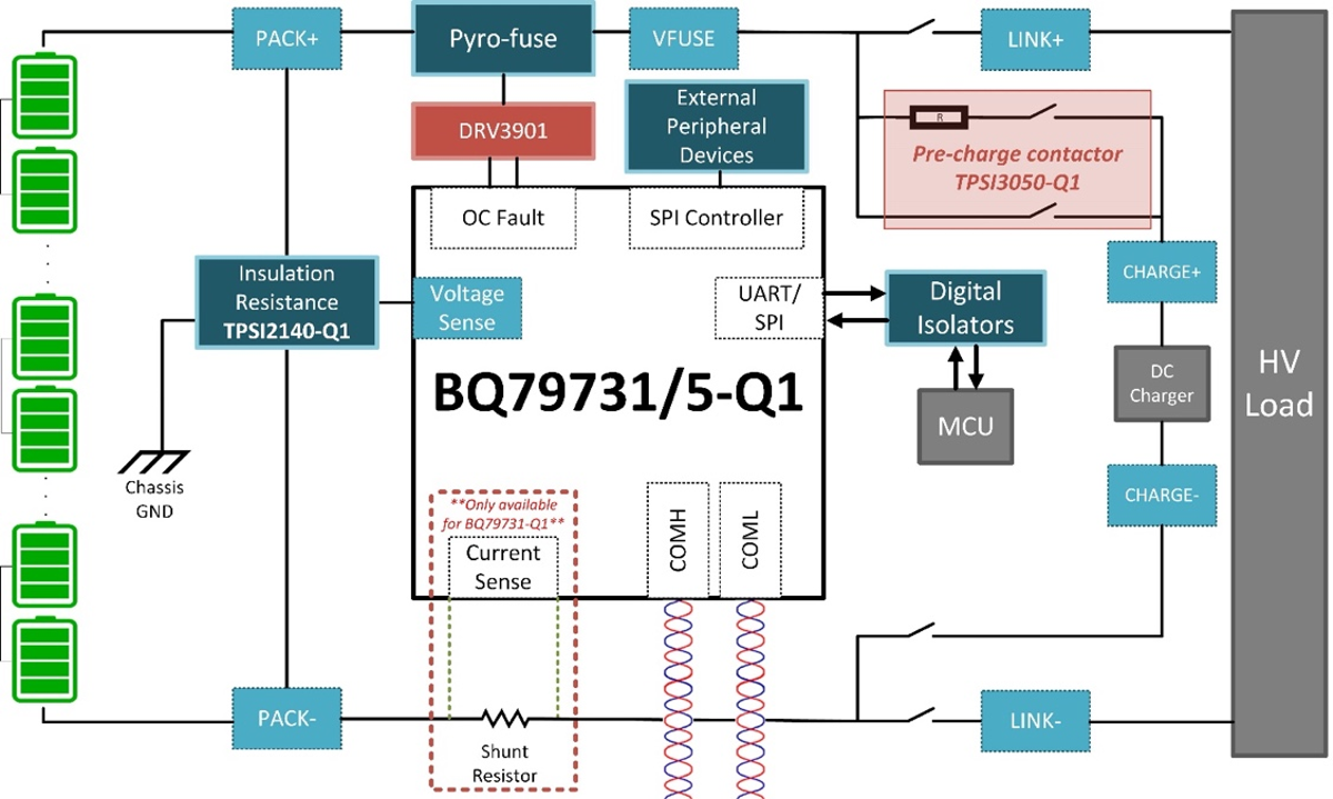
An intelligent battery junction box helps measure high voltages in the battery directly through a voltage, current and insulation resistance pack monitor. There are multiple voltage and current measurement channels available in a typical pack monitor, which can measure voltage across fuses and contractors and check the isolation. Figure 5 is a simplified system diagram of a battery junction box
 Figure 5 Simplified BJB system block diagram.
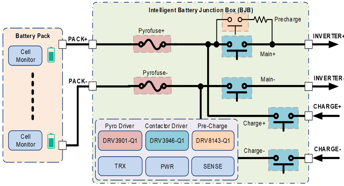
In the battery management systems there are two critical functions, battery disconnect and power distribution. An intelligent battery junction box incorporates digital control of contactor drivers and pyro fuse squib drivers to disconnect the battery pack to the EV system during a crash.
A high voltage battery disconnect can be handled with either a melting or pyro fuse. Higher current systems within vehicles introduce new conditions, causing the market to shift away from traditional melting fuses, which are triggered by an overcurrent thermal event, to pyro fuses, which are triggered through an MCU/HUB. Today, pyro fuses are driven by discrete, complex circuits that can be a source of inefficiency. TI’s single channel squib driver for automotive EV pyro fuse deployment, DRV3901-Q1, provides a highly-integrated, safety-developed solution for fast-acting overcurrent disconnection of the battery through a pyro fuse in place of traditional melting fuses systems.
High voltage power distribution contactors need to handle higher currents as well, but options are either limited and expensive or overly complex. Economized contactors have an additional high resistance economizer coil that is used to improve the efficiency of the main contractor by reducing current draw and heating while the contactor is energized. While these economized contactors sound like they are the solution improving system efficiency, there is a limited selection available today and they are often cost-prohibitive. Non-economized contactors in contrast, do not have this additional coil, which reduces the cost, but must be driven by a more complex discrete circuit in order to meet safety and efficiency standards. Texas Instruments has invested in reducing the complexity and cost of the circuitry needed to drive non-economized contactors while also improving the efficiency and robustness by developing the DRV3946-Q1, a fully integrated duel channel contactor driver that enables designer more freedom and design flexibility.
 Figure 6 Battery disconnect and power distribution for high power within BMS.
The battery pack uses mechanical contactors controlled by the pack monitor to connect or disconnect subsystems throughout the vehicle. Mechanical high-voltage contactors can weld or be damaged through arcing and pitting in the event of uncontrolled inrush current. Why Pre-Charge Circuits are Necessary in High-Voltage Systems explains the use of the TPSI3050-Q1 isolated switch driver to form a reliable solid-state relay for pre-charging in an automotive battery junction box. For intelligent battery junction boxes, the TPSI3100-Q1 can be implemented in such pre-charge applications to further enhance diagnostic capabilities with its integrated isolated comparators and fault reporting outputs. These features can be combined with over-current or temperature monitoring circuits to allow such fault detection circuitry to reliably feedback this information through the TPSI3100-Q1 and report any of these events to the pack monitor.
Both the positive and negative terminals of the high-voltage battery pack must be sufficiently separated from the chassis of the vehicle in order to protect the driver or a technician from potential electrical shock. Periodic monitoring of this separation is known as isolation check or insulation resistance monitoring. Solid-state relays such as the TPSI2140-Q1 connect and disconnect a known resistance value (such as 1 MΩ) in parallel to the unknown resistance value (between a battery terminal and chassis ground). By measuring the combined resistance using a pack monitor such as the BQ79731-Q1, you can determine whether the battery separation is within tolerance or potentially harmful.