SNIU052 November 2023
3.5 Registers Tab
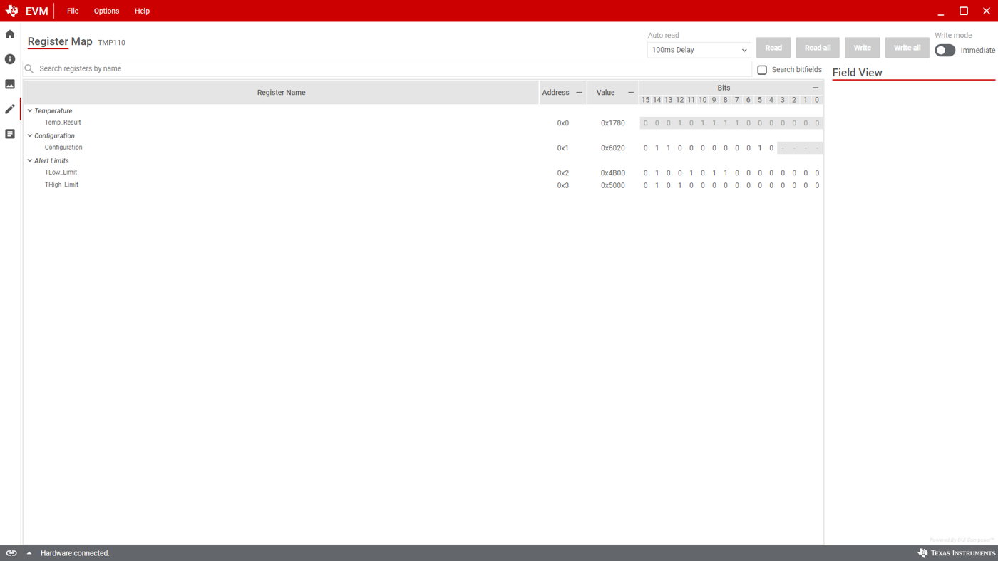
The Registers tab interacts with the registers and bits within the TMP110 device. For more information on each register/bit, click on a register name to see what each bit defines.
The Auto Read drop-down box configures polling of register contents. By default, the MCU polls the registers with a 100 ms delay. When Auto Read is Off, click Read Register to fetch the contents of the current register. Read All Registers can be used to fetch the contents of all registers at once.
By default, the Write Register button is grayed and disabled when the button is set to Immediate. Immediate mode triggers a Write operation each time a register is modified. When Deferred mode is selected, the Write Register button is enabled, and write operations are not performed unless the Write Register button is clicked.
These settings give the user total control over I2C Bus activity, and enable individual transactions to be easily observed with an oscilloscope, logic analyzer, or bus-sniffing device.
 Figure 3-5 Registers