SNOA949 May 2016 LDC1312 , LDC1312-Q1 , LDC1314 , LDC1314-Q1 , LDC1612 , LDC1612-Q1 , LDC1614 , LDC1614-Q1
4 Test Setup
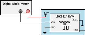
Duty-cycling the LDC was tested on the LDC1614 EVM with only one channel (Channel 0) enabled. The current flowing through the LDC1614 was measured using a Keysight (Agilent) 34410A digital multi-meter. The test setup is shown in Figure 5 and the testing conditions are given in Table 1.
 Figure 5. Test Setup
 Table 1. Testing Conditions
| Channel 0 | |
|---|---|
| Internal Reference Frequency (MHz) | 43.4 |
| Sensor Frequency (MHz) | 3.02 |
| Amplitude (VP) | 1.27 |
| Programmed SETTLECOUNT | 32 |
| Current Drive Setting (mA) (IDRIVE) | 0.196 |
The reference frequency was set by the internal oscillator and the current drive was set to achieve the recommended voltage amplitude for the oscillation waveform, which is between 1.2 and 1.8 VP.