SNVA866A February 2019 – January 2023 LM5155 , LM5155-Q1 , LM51551 , LM51551-Q1
- How to design an Isolated Flyback using LM5155
- Trademarks
- 1Introduction
- 2Example Application
- 3Calculations and Component Selection
- 4Component Selection Summary
- 5Small Signal Frequency Analysis
- 6Revision History
3.1 Switching Frequency
Selecting the switching frequency is the first step in the design process. Higher switching frequencies yield a smaller total solution size. However, the small size comes at the cost of increased switching losses, decreasing the efficiency of the regulator. Higher efficiency is achieved by selecting a relatively lower switching frequency but requires physically larger components. Harmonics of the switching frequency should be considered in designs that have strict EMC requirements. Equation 1 is used to set the frequency of the internal oscillator of the LM5155. The example application is selected to have a switching frequency of 250kHz.
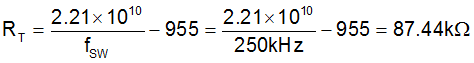
A standard value of 86.6kΩ is chosen for RT.
Note that the internal oscillator of the LM5155 can be synchronized to an external clock as described in the data sheet. The LM5155 has a maximum duty cycle limit that is frequency dependent. See the LM5155 data sheet for details on the maximum duty cycle limit.