SNVA870A March   2019  – April  2020 LM25143 , LM25143-Q1 , LM5143 , LM5143-Q1 , LM5143A-Q1


  1.   LM5143-Q1 4-phase Buck Regulator Design for Automotive ADAS Applications
    1.     Trademarks
    2. 1 High Density Reference Design Description
      1. 1.1 Typical Applications
      2. 1.2 Features and Electrical Performance
    3. 2 Design Specifications
    4. 3 Application Circuit Diagram
    5. 4 Photo
    6. 5 Test Data and Performance Curves
      1. 5.1 Conversion Efficiency
    7. 6 EVM Documentation
      1. 6.1 Schematic
      2. 6.2 Bill of Materials
      3. 6.3 PCB Layout
    8. 7 Device and Documentation Support
      1. 7.1 Device Support
        1. 7.1.1 Development Support
      2. 7.2 Documentation Support
        1. 7.2.1 Related Documentation
          1. 7.2.1.1 PCB Layout Resources
          2. 7.2.1.2 Thermal Design Resources
  2.   Revision History

Application Circuit Diagram

Figure 1 shows the schematic of an LM5143-Q1 based synchronous buck regulator (EMI filter stage not shown). Soft start (SS), restart (RES), and dither (DITH) components are shown that are configurable as required by the specific application.
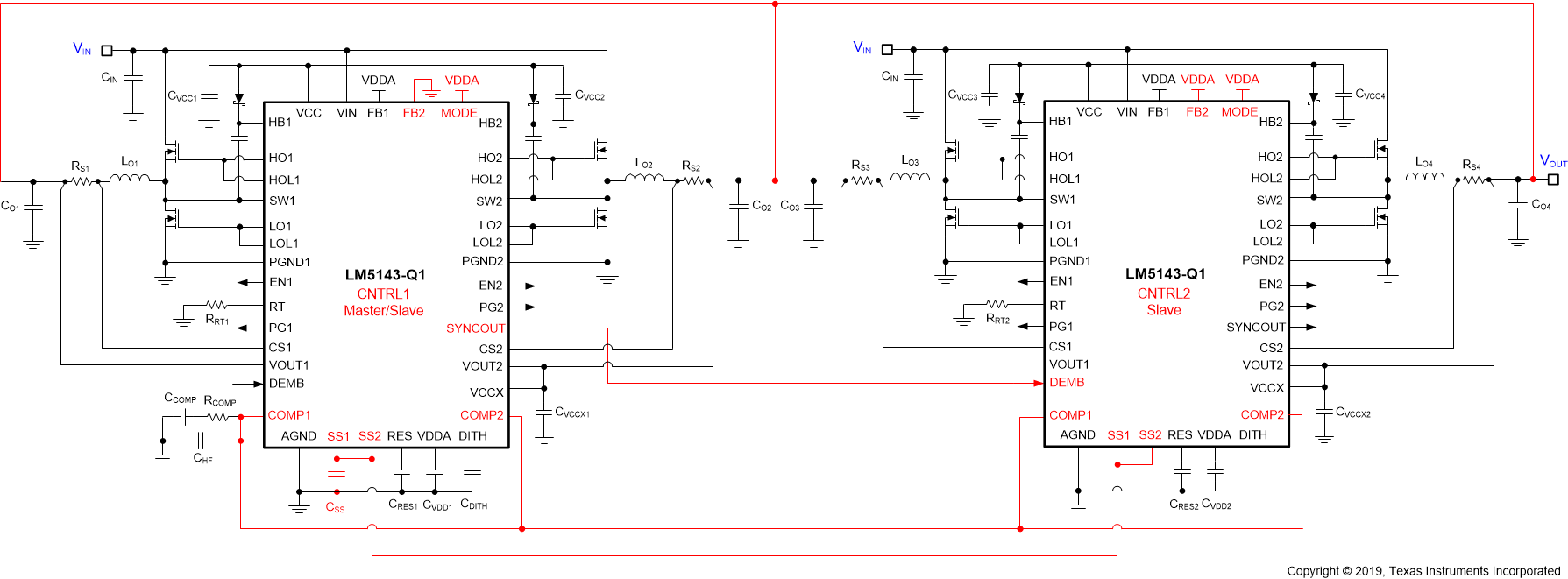
LM5143-Q1 LM5143-Q1-single-output-multiphase-operation-nva870.gifFigure 1. LM5143-Q1 4-Phase Synchronous Buck Regulator Schematic