SNVA885B September 2020 – November 2020 LP8732-Q1 , LP873220-Q1 , LP873222-Q1 , LP87322E-Q1 , LP87322F-Q1 , LP8733-Q1 , LP87332A-Q1 , LP87332B-Q1 , LP87332D-Q1 , LP87521-Q1 , LP87522-Q1 , LP87523-Q1 , LP87524-Q1 , LP87524B-Q1 , LP87524J-Q1 , LP87524P-Q1 , LP87525-Q1 , LP87561-Q1 , LP87562-Q1 , LP87563-Q1 , LP87564-Q1 , LP87565-Q1 , LP875701-Q1 , LP87702-Q1
Application Brief
Introduction
As industrial and automotive processor power requirements evolve each year, the demand for system adaptability and higher performance is greatly increasing. Applications, such as factory automation, building automation, advanced driver assistance system (ADAS), and infotainment and cluster require high-performance power solutions. In addition, next generation processors require designers to select optimized PMICs to meet specific power and sequencing requirements. Often times, these requirements change throughout the design cycle so it is important to have a power solution that is flexible and scalable. TI's portfolio of FlexPower, multiphase PMICs provide an adaptable and robust solution.
What is FlexPower?
FlexPower PMICs are flexible due to their ability to combine output buck converters to achieve higher output currents. Multiple FlexPower PMICs can also be stacked together to increase power-rail coverage, as shown in Figure 1-2. Each multi-phase FlexPower PMIC contains a pre-configured phase configuration with varying number of output rails to correspond with given voltage and current specifications. The phases of the LP8756x-Q1 can be combined to generate five different output combinations as shown in Figure 1-1.
 Figure 1-1 Output Configuration
Options
Figure 1-1 Output Configuration
OptionsWith the I2C configurable versions of the FlexPower devices, output settings can be configured at start-up via I2C. These devices, such as the LP873x-Q1 and LP8756x-Q1 families, are programmed with output rails initially disabled and are software configurable through I2C interface. As a result, customers can select a phase configuration that best matches customer requirements, then program the output voltages, current limits, and power-up and power-down sequence through the I2C communication at the device power using a local MCU. In addition to the I2C configurable option, TI released versions that are pre-programmed to power application-specific processors, such as, but not limited to, Jacinto™ processors, AWR/IWR radar sensors, and SitaraTM processors. In scenarios where custom application-specific settings need to be programmed into one-time programmable (OTP) default memory, contact your TI representative for more information on this programmability option.
Since the FlexPower PMICs are smaller (2–4 rail) PMICs, they can be interfaced and combined with other FlexPower PMICs to expand the power rail count to the user’s needed specifications, creating a distributed power solution. By being low rail count PMICs, FlexPower PMICs easily provide optimized solutions due to having no unused regulators.
Multiphase and Distributed Power Advantages
Due to the multi-phase capability of the DC/DC regulators and the smaller rail count of each device, FlexPower PMICs enable designers to adapt to their changing requirements by combining or separating various FlexPower PMICs depending on the application requirements. This reduces the potential of having unused regulators, ensuring a cost-optimized solution, no matter what the power requirements are. Multiple FlexPower PMICs can be combined to meet the exact needs of a SoC power requirement, without the need to implement an external sequencer or external fault monitor.
 Figure 1-2 Distributed Power
Example
Figure 1-2 Distributed Power
ExampleBy providing a distributed power solution, FlexPower PMICs help distribute thermals on the board. Traditional PMICs are highly integrated and, therefore, dissipate the heat of six or more regulators in the same package. In this case, the concentrated thermal dissipation may conflict with neighboring components, potentially hindering the overall system performance or capability. FlexPower PMICs resolve this issue by being a scalable multi-chip solution consisting of low-rail count ICs, which better distributes the thermal dissipation across the board as shown in Figure 1-2. Moreover, the smaller footprint of each individual flexpower PMIC enables more layout flexibility, allowing designers to collocate the PMIC next to the point of load.
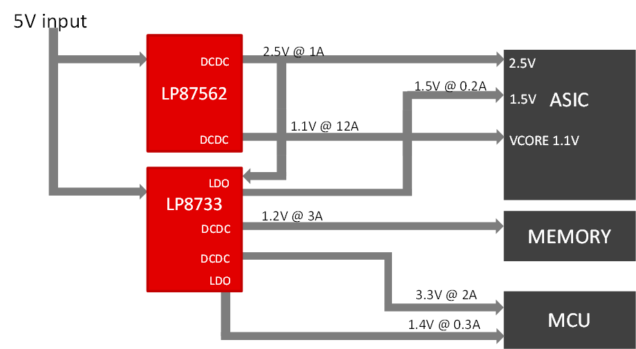
During the design process, the user must first select a device that meets the specific power requirements of the system's FPGA or processor; however, the power requirements may change multiple times before the design is finalized. For example, assume the user's preliminary power estimate is to have four rails with the following specifications as shown in Figure 1-3. After testing and realizing the rails need to be tweaked to power the required processor, the user makes the following changes for the design verification phase, as shown in Figure 1-3. These changes can easily be made with a change to the MCU code.
 Figure 1-3 I2C Configuration
Design Process
 Figure 1-4 Summary of FlexPower
Benefits
Figure 1-4 Summary of FlexPower
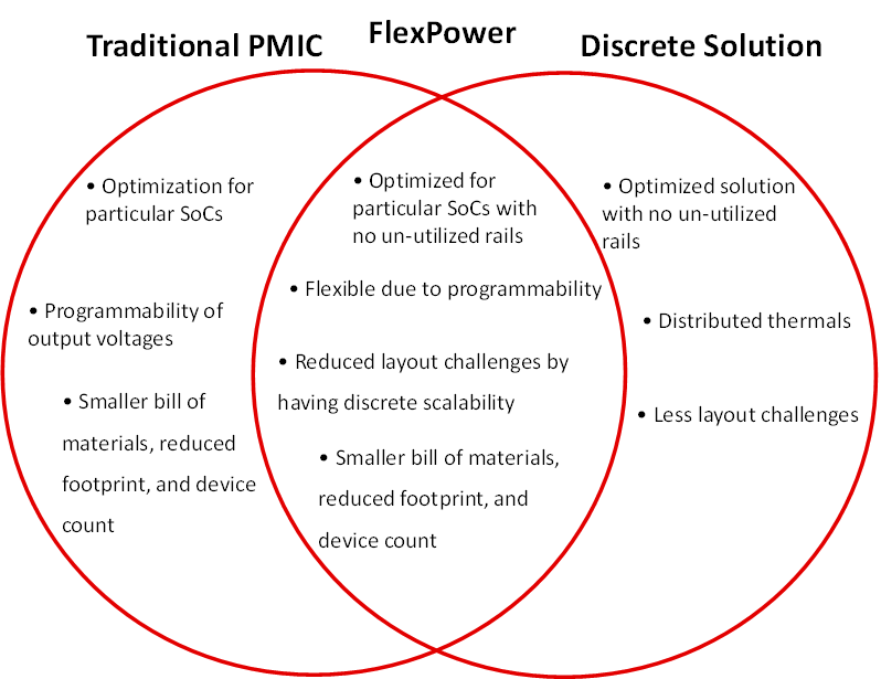
BenefitsBy providing the scalability of discrete components, and sequencing and monitoring features of a traditional PMIC, FlexPower solutions provide the best of both architectures as shown in Figure 1-4. Also, with software-configurable options, FlexPower PMICs allow reduced design-cycle time and easy customization of the PMIC, ensuring the PMIC is optimized for the specific power needs of the project.
| Device | Vin Range | Number of Power Rails | Max Current Per Channel | Vout Range | Features | Package |
|---|---|---|---|---|---|---|
| LP8732-Q1 | 2.8 V–5.5 V | 2 DC/DC Multiphase Buck Regulators, 2 LDOs | 2 A | 0.7
V–3.36 V (Buck) 0.8 V–3.3 V (LDO) |
PGOOD, I2C | 5×5-mm QFN |
| LP8733-Q1 | 2.8 V–5.5 V | 2 DC/DC Multiphase Buck Regulators, 2 LDOs | 3 A | 0.7
V–3.36 V (Buck) 0.8 V–3.3 V (LDO) |
PGOOD, I2C | 5×5-mm QFN |
| LP8752-Q1 | 2.8 V-5.5 V | 4 DC/DC | 4 A, 10 A total | 0.6V-3.36 V (Buck) | PGOOD, I2C | 4×4.5-mm QFN, HotRod |
| LP8756-Q1 | 2.8 V–5.5 V | 4 DC/DC Multiphase Buck Regulators | 4 A, 16 A total | 0.6 V–3.36 V (Buck) | PGOOD, I2C | 4×4.5-mm QFN, HotRod |
| LP875701-Q1 | 2.8 V-5.5 V | 1 4-phase Buck Regulator | 10 A | 1.0 V (Buck) | PGOOD, I2C Improved DC and AC Accuracy | 4×4.5-mm QFN, HotRod |
| LP8770-Q1 | 2.8 V–5.5 V | 2 DC/DC Multiphase Buck Regulators, 1 5 V Boost Regulator | 3.5 A | 0.7 V–3.36 V (Buck) | PGOOD, I2C, Independent Vref, Watchdog, and External voltage monitoring | 5×5-mm QFN |
| LP8758-E3 | 2.5 V-5.5 V | 4 DC/DC Regulators | 4A | 0.5 V-3.36 V (Buck) | PGOOD, I2C | 2.92×2.17-mm DSBGA |
| LP8733 | 2.8 V-5.5 V | 2 DC/DC Multiphase Buck Regulators, 2 LDOs | 3A | 0.7 V-3.36 V (Buck) 0.8 V-3.3 V (LDO) | PGOOD, I2C | 5×5-mm QFN |