SNVU699 October 2020
3 EVM Theory and Operation
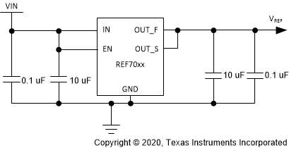
The following schematic is representative of the REF70EVM.
 Figure 3-1 REF7025 Schematic
The REF70EVM is designed to allow users to evaluate the configuration in Figure 3-1. With the provided footprints, a user can change the passive components to better suit their application. As shown in Figure 1-2, the EVM is designed to allow users to evaluate the REF70 in FKH. This EVM also has the land pattern for the REF70 in DGK which allows users to test the device in their system with the provided pins.