SPRACY7 October 2021 TMS320F2800132 , TMS320F2800133 , TMS320F2800135 , TMS320F2800137 , TMS320F2800152-Q1 , TMS320F2800153-Q1 , TMS320F2800154-Q1 , TMS320F2800155 , TMS320F2800155-Q1 , TMS320F2800156-Q1 , TMS320F2800157 , TMS320F2800157-Q1 , TMS320F280033 , TMS320F280034 , TMS320F280034-Q1 , TMS320F280036-Q1 , TMS320F280036C-Q1 , TMS320F280037 , TMS320F280037-Q1 , TMS320F280037C , TMS320F280037C-Q1 , TMS320F280038-Q1 , TMS320F280038C-Q1 , TMS320F280039 , TMS320F280039-Q1 , TMS320F280039C , TMS320F280039C-Q1
3.2.4 Rotate Right Once - CPOL=1, CPHA=0
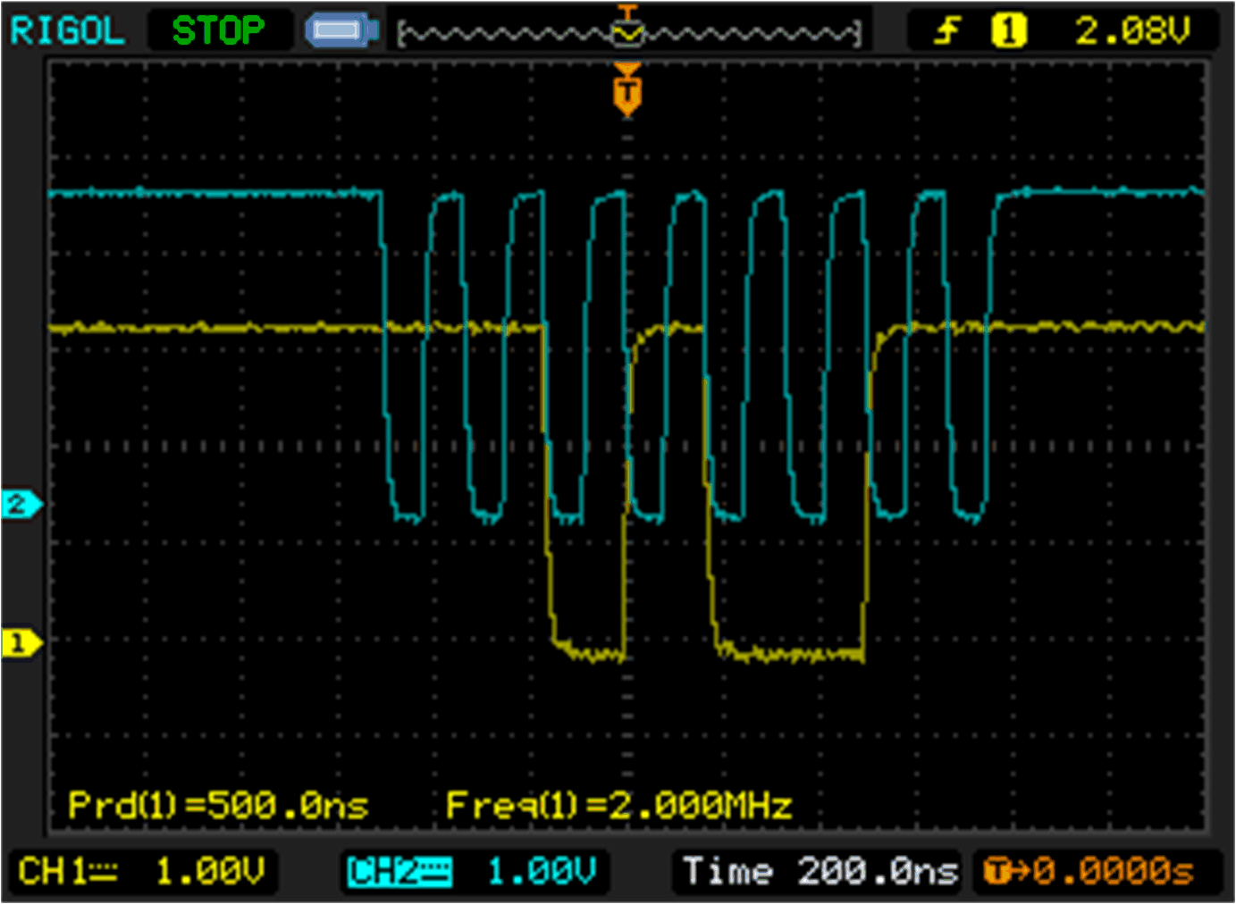
The clock and data bit stream for CPOL=1 and CPHA=0 is shown below:
//
// Data
//
#define SIG_GEN_DATA0_0_15    0b1110000110011111U

//
// Clock - Data latched on rising edge, during idle CLK is HIGH
//
#define SIG_GEN_DATA0_16_31   0b0101010101010101U
The data bit stream in this mode is the same as CPOL=0, CPHA=0. The clock bit stream is inverted to place rising edges in between duplicated data stream bits.
 Figure 3-12 Rotate Right Once - CPOL=1,
CPHA=0
Figure 3-12 Rotate Right Once - CPOL=1,
CPHA=0Next, creating the same signals using the SIGGEN module in SHIFT RIGHT ONCE mode will be discussed.