SPRAD24 august 2023 AM2631 , AM2632 , AM2632-Q1 , AM2634 , AM2634-Q1
- 1
- Abstract
- Trademarks
- 1Introduction
- 2AM263x Overview
- 3Guide to Running TIDM-02014 Traction Inverter
- 4Brief Guide to Code Migration
- 5Summary
- 6References
2.1 AM263x Control Card and Traction System Framework
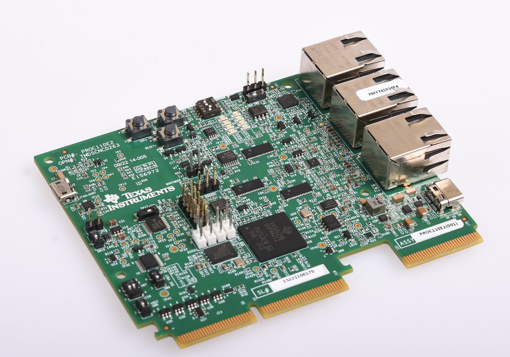
The AM263x Control Card Evaluation Module (EVM) is an evaluation and development board for the Texas Instruments Sitara™ AM263x series of microcontrollers (MCUs). This EVM provides an easy way to start developing on the AM263x MCUs with on-board emulation for programming and debugging as well as buttons and LEDs for a simple user interface. The control card also enables header pin access to key signals through the use of a high speed edge connector (HSEC) that can directly be plugged onto the TIDM-02014 main control board.
 Figure 2-1 AM263x Sitara Control
Card
Figure 2-1 AM263x Sitara Control
CardThe traction framework includes the resources highlighted in Figure 2-1 and is built into the traction system in Figure 2-2. TIDM-02014 is the traction inverter reference design hardware. It includes a power stage, gate drivers, current and voltage sampling, resolver analog front end, control system power tree and connection interfaces. The motor includes a resolver taking sine wave excitation and sending modulated feedbacks for position sensing. Field Oriented Control is implemented with Cluster-0 Core-0. The real-time control section in ADC INT1 is allocated to TCM for the most deterministic execution time.
 Figure 2-2 Traction Framework
Resources
 Figure 2-3 Traction System
Diagram