SPRUII1A November   2017  – January 2020


  1.   Fusion Application Board
    1.     Trademarks
    2. 1 Introduction
    3. 2 Overview
      1. 2.1 Fusion Application Board
      2. 2.2 Fusion Board Features
    4. 3 Hardware
      1. 3.1  Hardware Architecture
        1. 3.1.1 Fusion Application Board With Component Identification
      2. 3.2  TDAx EVM Compatibility
      3. 3.3  Fusion Power
      4. 3.4  DS90UB960 Modes
        1. 3.4.1 Power over Coax (PoC)
      5. 3.5  I2C Addressing
        1. 3.5.1 Multiple Device Addressing (Aliasing)
        2. 3.5.2 I2C Bus Switches and Connections
      6. 3.6  EVM Interface
      7. 3.7  Sensor Connection
      8. 3.8  MSP430™ Microcontroller
      9. 3.9  Configuration Options
        1. 3.9.1 Dipswitch (S3)
        2. 3.9.2 Bank 1 Power (J27)
        3. 3.9.3 Bank 2 Power (J22)
      10. 3.10 Status LEDs
      11. 3.11 External Interfaces
    5. 4 Image Sensor Module (Optional)
      1. 4.1 OV2775 Image Sensor
      2. 4.2 DS90UB953-Q1 Serializer
    6. 5 Getting Started
      1. 5.1 Powering Up the Fusion Application Board
  2.   Revision History

Fusion Application Board With Component Identification

Figure 3 shows the major connectors and components on the top side of the board.
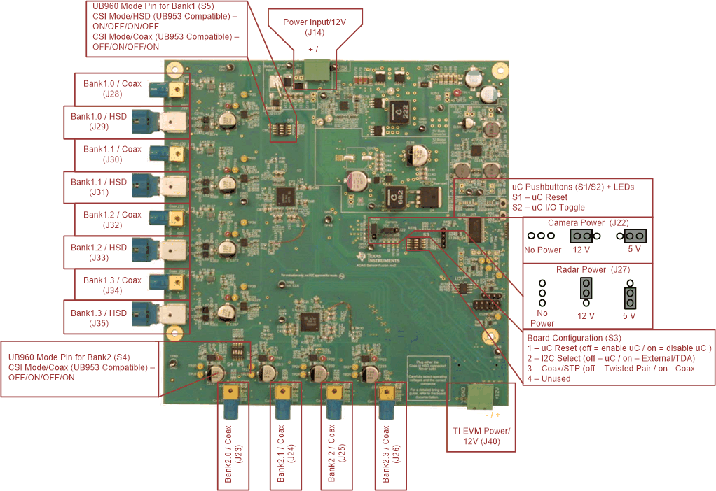
Board_with_component_identification.gifFigure 3. Board With Components Identifications

The CSI-2 connector is placed on the bottom side of the board; this is the connector that makes an interface with the TI compatible EVM (see Figure 4).
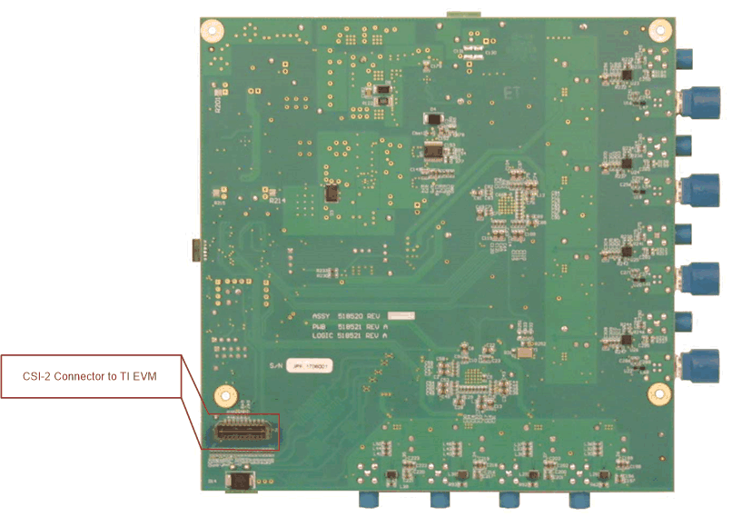
Bottom-Side-of-Fusion-board.gifFigure 4. Bottom Side of Fusion Board With CSI-2 Connector