SPRUII1A November 2017 – January 2020
-
Fusion Application Board
- Trademarks
- 1 Introduction
- 2 Overview
- 3 Hardware
- 4 Image Sensor Module (Optional)
- 5 Getting Started
- Revision History
3.5.2 I2C Bus Switches and Connections
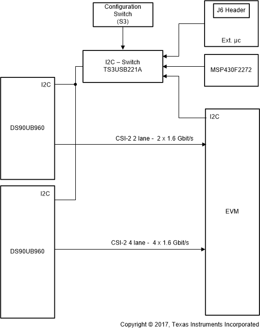
There are three options for control and configuration of the DS90UB960-Q1 device, including the EVM, MSP430, or an external microcontroller. Selection of what option controls is done through a combination of configuration switches and software. By default, the switch controls selection; however, there are several mechanisms to override the switch setting (MSP430 GPIO, EVM GPIO, or header J6/J11). The external microcontroller (J6) has been broken out on the Fusion board to identify the I2C host in the system and to connect to an external microcontroller if applicable (see Figure 6).
 Figure 6. Block Diagram of I2C Assignments
 When open, S3 position 2 selects I2C to the MSP430 microcontroller (see Table 3). When closed, S3 position 2 selects I2C to be used on the EVM or external microcontroller.
Table 3. I2C Host Configurations
| I2C Host | S3.1 | S3.2 | S3.3(3) | S3.4 | J6.1 | J6.1 | J6.3 | Details |
|---|---|---|---|---|---|---|---|---|
| EVM | On | On | Optional | N/A | Open | Open | Open | J1.20(1) must be set high to override the switch. Set from the TDA2Px EVM. For specific settings, see the device-specific EVM User's Guide. |
| MSP430 | Off | Off | Optional | N/A | Open | Open | Open | P2.7 on the MSP430 must be set low. P2.5 must be set high. |
| External microcontroller | On | On | Optional | N/A | Low | High | High | J6 and J11 or J15 external(2). The external MCU overrides settings through J6. |
Table 4 lists the onboard I2C switch details.
Table 4. Onboard I2C Switches
| Switch Name | Component Name | J6 Pin Number | Function |
|---|---|---|---|
| I2C_SW_SOC | U4 | J6.1 | Enables I2C communication with the EVM. |
| I2C_SW_EXTERNAL | U6 | J6.2 | Enables I2C communication with the external. |
| I2C_SW_UB960 | U5 | J6.3 | Enables I2C communication with the DS90UB960 device. |
- I2C_SW_SOC: Depending on when this switch is closed, the SoC can either initialize the board, or just control the sensors after board initialization is completed. Writing I2C commands into the DS90UB960 device during normal operation configures the external sensors. The DS90UB960 device passes the commands onto one of the sensors addressed. Routing of the commands takes place by use of the alias address scheme discussed earlier. When this switch is open, all SoC traffic is isolated from the board. This allows the local MSP430 or the external microcontroller to be the host.
- I2C_SW_External: When the switch is closed, it allows the external microcontroller to take over as the host of the I2C bus. If an external microcontroller is used, the MSP430 and SoC must avoid using the bus, per software configuration. When the switch is open, either the MSP430 or the SoC is the I2C host in the system.
- I2C_SW_UB960: When the I2C switch is closed, the main I2C bus on the DS90UB960 is connected to the main I2C bus on the board. This switch must be closed for all configurations to the DS90UB960 and all external sensors as well.