SPRZ408D June 2014 – June 2021 AM4372 , AM4376 , AM4377 , AM4378 , AM4379
- Trademarks
- 1Introduction
- 2All Errata Listed With Silicon Revision Number
-
3Usage Notes and Known Design Exceptions to Functional Specifications
- 3.1 Usage Notes
- 3.2
Known Design Exceptions to Functional Specifications
- 3.2.1 Advisory List
- Advisory 1
- Advisory 2
- Advisory 3
- Advisory 4
- Advisory 5
- Advisory 6
- Advisory 7
- Advisory 8
- Advisory 9
- Advisory 10
- Advisory 11
- Advisory 12
- Advisory 13
- Advisory 14
- Advisory 15
- Advisory 16
- Advisory 17
- Advisory 19
- Advisory 20
- Advisory 21
- Advisory 22
- Advisory 24
- Advisory 25
- Advisory 26
- Advisory 27
- Advisory 28
- i2223
- i2224
- i912
- i2225
- i2226
- 4Revision History
Advisory 19
TSC_ADC: False Pen-up Interrupts
Revisions Affected
1.1, 1.2
Details
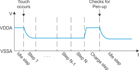
The touchscreen controller (TSC) determines the pen state (up or down) by checking the respective analog input (AIN0 for 4-wire or AIN4 for 5-wire) voltage level immediately after the Charge step. This does not provide enough time for the analog input voltage to return to the normal Pen-down voltage before testing the pen state. This will cause the TSC to generate a false Pen-up interrupt if the Charge step is enabled with the strong pull-up turned on when using hardware synchronized steps. Figure 3-4 illustrates the effect on the analog voltage when constant pen pressure is applied to the touchscreen and held through the Charge step.
 Figure 3-4 TSC Generates False Pen-up Interrupt
Workarounds
There are two possible workarounds for this problem:
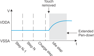
- The first workaround is implemented by configuring the Charge step exactly like the Idle step, where the internal strong pull-up is not turned on. This workaround will remove the strong pull-up on the analog input during the Charge step and leave only the internal weak pull-up. The weak pull-up is not strong enough to effect the normal Pen-down voltage. Therefore, the voltage applied to the analog input will not rise and cause the TSC to generate a false Pen-up interrupt. There is a drawback to this approach; this workaround will cause the Pen-down event to remain active until the weak pull-up turned on in the Idle step charges the touchscreen capacitance, as shown in Figure 3-5.
 Figure 3-5 Pen-down Remains Active in Idle Step
 - Another method is available for 4-wire touchscreen implementations. It this case, it is possible to enable and configure one of the 16 steps to emulate the Charge step with the strong pull-up turned on as the step before the actual Charge step that has been configured like the Idle step with the strong pull-up turned off. The advantage of this implementation is that you are able to charge the touchscreen quicker and avoid the possible false Pen-down interrupts. The disadvantage is that you lose one of the 16 programmable steps and during this step there will be a garbage result stored in the FIFO. You will need to set the Step_ID_tag bit in the CTRL register so that you can identify the garbage result in the FIFO and discard it.