SSZT884 November   2017


  1.   1
  2.   2
    1.     3
    2. 1. Magic smoke is real and you need to embrace it.
    3. 2. You’ll never be alone when you work in isolation.
    4. 3. Pease Isn’t a Typo.
    5. 4. Clocks Are No Good at Telling Time.
    6. 5. There Is a Lot of Drawing Involved for a Field This Technical.
    7. 6. V = IR Is Always the Answer.
    8. 7. Those Formulas from Engineering 101 Still Come in Handy Today.

GUID-13F5674A-2D82-4321-9EB7-F3589A2857CC-low.jpg

Matt Hein

I’m sure you’ve been asked at some point what you do for a living. For me, it is normally an odd conversation:

Them: What do you do?

Me: I work at Texas Instruments.

Them: So you make the calculators!

Me: No, actually I work in Analog.

Them: What’s an analog?

Me: Analog is when you deal with continuous signals.

Them: Why would you do something like that?

Me: Because you need to design analog circuits to process real-life voltages and currents.

Them: Why would you need to? I would just let the analog process itself.

Me: [long silence] … Just kidding, I make the calculators.

This exchange is proof that analog engineers really do deal with a subject with which many people are completely unfamiliar. We have concepts, languages and heroes that are unique to us, that set us apart and give us common ground. So in this post, I want to talk about a few things that come to mind when I think about things that only an analog engineer would understand.

1. Magic smoke is real and you need to embrace it.

Every integrated circuit or electronic component operates using a little-known mystical wonder. We call it the “magic smoke.” This smoke is ethereal, sublime and not completely understood by the scientific method. Practically, however, it is a distinct and critical part of the component. There is no class that you can take and no book that you can read about magic smoke, but its effects are well-known in the industry.

Magic smoke works like this:

  • It is sealed into the component at manufacture.
  • The component operates as long as the magic smoke is contained inside of the component.
  • If the magic smoke is ever allowed out of the component, the component will no longer function (Figure 1).
  • Much like a can of worms, you can’t put magic smoke back into the component.

Therefore, by the observed effects of magic smoke, you can conclude that it is essential to component operation. Common causes of magic smoke release include (but are not limited to) overvoltage stressing, overcurrent stressing, reversed supply, overheating or incorrect wiring.
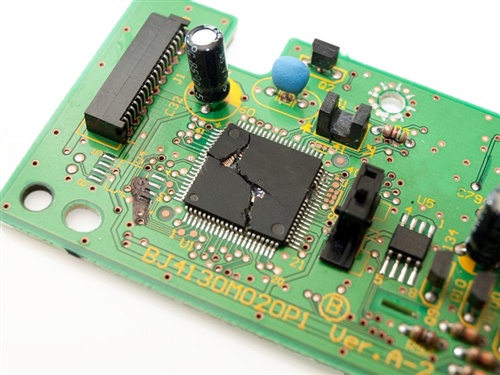
GUID-208488BF-4D09-41F1-88AB-C720217C727B-low.jpg Figure 1 The Hermetically Sealed Smoke Container Is Breached, Resulting in a Component That No Longer Works

2. You’ll never be alone when you work in isolation.

Many electronic systems have multiple different supply “zones.” For example, in a compressor circuit, there will be a high-voltage zone that is several hundred volts to supply power to the motor and a low-voltage zone where the control circuits live and work. To improve the reliability of these systems, designers use a concept called isolation.

Isolation is a way to transport data and power between high- and low-voltage circuits while preventing hazardous or uncontrolled transient current from flowing in between the two. Isolation protects circuits and helps them withstand high-voltage surges that would damage equipment or harm humans – even smart humans like analog engineers. Most sane lab practices require that you not be alone in the lab when working on systems that operate at potentially dangerous high voltages. So if you are working in isolation, grab a buddy and stay safe!

3. Pease Isn’t a Typo.

One of the greatest legends of analog design was the late Bob Pease. He’s credited with developing more than 20 integrated circuits, many of them used for decades in the industry. Bob chronicled his design experiences in a column called “Pease Porridge,” which ran monthly in Electronic Design magazine (Figure 2 shows one of Bob’s quips, signed with his initials, RAP). He also hosted the semiconductor industry’s first online webcast, tailored specifically for analog design engineers.

GUID-554D67C1-61F8-4D14-9E6E-0E022669B9A0-low.jpg Figure 2 If You Don’t Understand the Joke, Then You Need to Spend More Time in the Lab

4. Clocks Are No Good at Telling Time.

Clocks are possibly the most ironically named analog components because a clock won’t give you the time of day. A “clock” is in reality an oscillator typically used to generate a consistent, stable frequency. Clocks can be a key element of analog design because of interference to and from the clock signal. A clock signal propagating across a board adds noise and accumulates delay. Meanwhile, the clock signal induces noise onto other nets on the board. Clocks can be messy if not done properly, so it is critical that you understand the purpose of oscillators, generators, buffers and jitter cleaners in order to optimize your system.

5. There Is a Lot of Drawing Involved for a Field This Technical.

Analog design engineers love to draw. We love to pick up dry erase markers and draw squiggly lines all over a white board. We draw in a language unique to us and undecipherable to the uninitiated (Figure 3). Every major component in a system has its own special symbol, ranging from simple resistors and capacitors up to complicated blocks like analog-to-digital converters (ADCs) and digital-to-analog converters (DACs). These symbols bring meaning and functionality to a circuit long before anything physical is actually made and provide a platform for discussion, starting with the phrase “And this is how it works …”

GUID-A24B1F88-6CB3-4FEF-9481-1C2F46CE7B2D-low.jpg Figure 3 The Secret Analog Language

6. V = IR Is Always the Answer.

It is humorous how useful simple concepts can be. Analog design is home to some very complicated integrated circuits: sigma-delta ADCs, RF amplifiers, digital isolators, etc. Yet the most common design equation is Ohm’s law, a relationship that most people learn in high school or even earlier.

Ohm’s law states that V = IR, or that voltage is equal to current times resistance. Undoubtedly, most of you are rolling your eyes at the fact that I just wasted a whole sentence to describe Ohm’s law, which everyone already knows.

Let’s take a look at some examples of analog design that don’t require a doctorate in mathematics to solve:

  • Current shunt amplifier: A 10mΩ resistor (R) is placed in line with a current up to 10A (I), and the 0-0.1V (V) is amplified and measured.
  • In a precision DAC, at a 5mA (I) load the output drops by 120mV (V), meaning that the output impedance (resistance) is about 24Ω (R).
  • In a motor gate driver, a MOSFET overcurrent monitor trips at 0.5V (V), meaning that a MOSFET with an on-resistance of 20mΩ (R) has an overcurrent threshold of 25 A (I).

7. Those Formulas from Engineering 101 Still Come in Handy Today.

Moving on from Ohm’s law can be the most jarring event in an analog engineer’s life. While you can solve many problems with V = IR, plenty of designs require more knowhow. From remembering capacitor types, to the equation for discharging a resistor-capacitor (RC) circuit, to calculating noise bandwidth, there can be a lot to keep track of.

Of course no analog designer should wade into these waters alone, so TI put together the Analog Engineer’s Pocket Reference (Figure 4). Reference guides for analog have been around for a long, long time and are a tried-and-true method of giving you all the tips, tricks and facts. I would say that a good reference guide is all you need, but the most critical element to any design is your creativity, ingenuity and excitement for analog.

GUID-AE39E418-991E-42F6-99BC-ED71E4A88D2C-low.jpg Figure 4 Some Things Never Change

Are There Any More Things That Only an Analog Engineer Would Understand? Comment below and Let Us Know If You Have Any Unique Experiences in Analog.