SSZTC65 september 2015 ADC12J4000 , DAC38J84
** This is the sixth post in a new RF-sampling blog series that’ll appear monthly on Analog Wire **
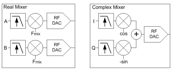
In a communication system the digital processor feeds or receives digital data at baseband frequencies; this keeps data rates at reasonable speeds for processing. With traditional transceiver architectures the data converter operates with low frequency analog signals. An additional analog mixer is elsewhere in the line-up to convert to or from a higher frequency. With an RF Sampling data converter, the analog signals are directly generated or received at high frequencies. These data converters are equipped with digital mixers to move the baseband signal to or from the desired high frequency location. For simplicity, I will focus on the digital-to-analog converters (DACs), although the concepts are equivalent in analog-to-digital converters (ADCs) with the signal flow in the opposite direction. There are two primary options for digital mixers: real-in to real-out or complex-in to real-out. Figure 1 illustrates the two options in a DAC.
 Figure 1 Real and Complex Digital
Mixers
Figure 1 Real and Complex Digital
MixersThe complex mixer is more advantageous because the input I and Q data occupies half the bandwidth of the output signal and the image and carrier components are naturally suppressed. Unlike its analog equivalent, the digital mixer is near perfect, so the impairments that translate to imperfect sideband suppression or carrier feed-through are not present.
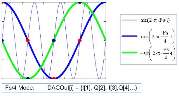
The digital mixer, like its analog equivalent, needs an oscillator source for the mixing operation. An easy implementation is to use a fixed frequency based on the data converter’s sample clock. A coarse mixer using a fixed oscillator frequency at the sampling rate divided by four (Fs/4) is very easy to implement. The complex mixer multiplies the I and Q input data by quadrature tones: cosine and sine. When using Fs/4 mixing, the multiplication factors simplify to either 1, 0 or -1: no actual multiplication is required. You can derive the output by extracting the proper data point within the I/Q data stream, which is a simple approach that minimizes current consumption. Figure 2 illustrates the operation for Fs/4 mixing and the pattern for the output.
 Figure 2 Output Pattern for Complex
Fs/4 Mixing
Figure 2 Output Pattern for Complex
Fs/4 MixingWhen you need more flexibility, a numerically controlled oscillator (NCO) provides the oscillator function. The NCO is programmed to any arbitrary frequency within the device’s Nyquist zone. This allows the signal to be moved via software to any RF band. The NCO uses a fast look-up table to create the oscillator signal. A common implementation utilizes a 32-bit to 48-bit NCO that can provide sub-hertz frequency resolution. In addition, the mixer incorporates phase-adjustment capabilities. Figure 3 is a block diagram of the NCO.
 Figure 3 48-Bit NCO Block
Diagram
Figure 3 48-Bit NCO Block
DiagramThe digital mixer provides superior performance compared to its analog counterpart. Users can program the exact frequency output on the fly. No hardware modifications are needed. DACs like the DAC38J84 employ a full complement of coarse and fine mixer options for the transmitter. An ADC like the ADC12J4000 incorporates a complex mixer for use on the receiver.
For added flexibility in software-defined architectures, the converter can employ multiple digital mixers so that multiple signals can be independently moved in frequency. This opens up opportunities to support multiband applications very easily and change frequency bands in real time as needed.
In next month’s post, I will discuss interleaving to achieve high-sampling-rate RF sampling ADCs.
Additional Resources
- Learn more about designing with data converters in TI’s Data Converter Learning Center.
- Watch and learn more about digital mixer usage in the RF sampling series video: Managing data rates.
- Read other blog posts in the RF sampling series.